


VILTER MANUFACTURING CORPORATION
VILTER MultiCylinder Compressor
400 Series VMC 2/01
SERVICE - 20 - Replaces all Previous Issues
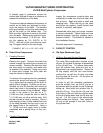
A. Disassembly
After the cylinder covers, valves and handhole
cover have been removed, the first step in re-
moving the piston and rod assembly is to remove
the Palnut
®
locknuts on the rod bearing bolts.
Then, remove the plain nuts and slide the bear-
ing cap off of the nuts. The Palnut locknut is not
used with this type of locknut.
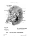
Handle the bearing cap carefully to avoid dam-
age to the bearing half insert. Push the rod and
piston out through the top of the cylinder. Avoid
possible mixing with components. Keep all parts
together in relation to their position in the com-
pressor. Connecting rods and rod caps are
match marked to aid in reassembly. On reas-
sembly, all parts must be installed in the same
position in the compressor.
As soon as the parts are removed from the com-
pressor, they should be thoroughly cleaned with
a suitable refrigeration parts cleaner. Once the
oil film is removed, the bare metal is subject to
rust. This reaction can start immediately. There-
fore, lubricate the surfaces of the parts lightly
with clean compressor oil immediately after
cleaning.
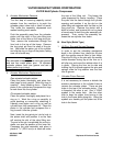
The tabs on the bearing half insert fit into the re-
cess in the rod and rod cap, and the inserts can
be slipped out without difficulty. To replace the
rod bearings, it is necessary to change the in-
serts only and not the entire rod.
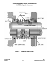
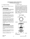
1. 440 & 450 VMC Compressors Only
To remove the rod from the piston, take out
the piston pins. Remove the spring locks
from the pin hole on each side of the piston
and slide out the pins. If this cannot be ac-
complished by hand, it may be necessary to
force the pin out with a brass rod and ham-
mer. Be careful not to damage spring lock
grooves. To remove the piston rings, use
the ring expander. Caution should be exer-
cised to prevent the rings from scoring the
piston.
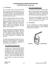
2. 450XL VMC Compressor Only
If the piston rings are to be removed, wrap a
piece of thin shim stock around the piston.
Work the rings carefully out of their grooves
and onto the shim stock. They can then be
worked down over the piston. Caution must
be exercised to prevent breaking the rings.
The piston and connecting rod assembly
should not be disassembled further. It is
furnished only as a complete assembly and
should not be worked on in the field.
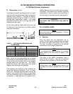
B. Reassembly
All new compressors use three compression
rings and one oil control ring. When replacing
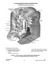
rings, use the ring expander. Check the grooves
to make sure they are clean.
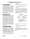
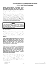
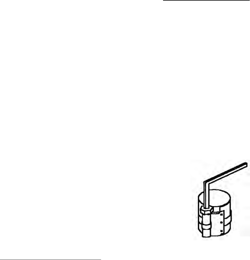
FIGURE 10. PISTON RING COMPRESSING
TOOL