


VILTER MANUFACTURING CORPORATION
VILTER MultiCylinder Compressor
400 Series VMC 2/01
SERVICE - 25 - Replaces all Previous Issues
A. General
Removing the crankshaft from the compressor is
basically the same for all units, regardless of
size. Because of a center bearing on all 12 and
16 cylinder compressors and the radius the 8 cyl-
inder throws on the crankshaft, an extra step
must be taken. A crankshaft may be removed
from either end of the compressor. It is, how-
ever, easier to take the crankshaft out of the
drive end of the frame. If the crankshaft is taken
out of the pump end, the entire shaft seal must
be removed.
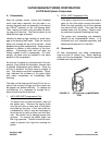
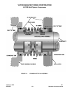
B. Removal From Drive End
Remove any connections that will hinder the re-
moval of the front bearing housing. When dis-
connecting the front oil line, be prepared to catch
approximately 1 gallon of oil. Remove the shaft
seal and inner retainer.
Replace the two
5
/
8
” (15.88 mm) x 4” (101.6 mm)
socket head screws with threaded studs to sup-
port the front housing during removal. Remove
the 6
5
/
8
” (168.28 mm) x 2” (50.8 mm) cap screws
that hold the housing to the frame. Using the 4”
(101.6 mm) socket head screws, insert them into
the tapped holes on both sides of the housing to
aid in the removal of the front housing from the
frame and off the front bearing. During this proc-
ess, the housing will have a tendency to hang-up
on the outer diameter of the bearing, thus pulling
the entire shaft with it and possibly disengaging
from the rear housing. Care must be taken to
prevent this from happening. While the front
housing is being removed, push on the crank-
shaft to be sure it is staying in the rear housing.
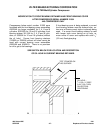
On a 458XL and 4516XL compressor, the rear
housing will have to be removed, because the
radius of the counterweight is larger than the ra-
dius of the front housing bore. Thus, the shaft
will be hindered from coming straight out of the
frame.
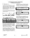
On a 12 or 16 cylinder compressor, the center
bearing must be freed. At this time, remove the
oil circuit piping tee in the middle of the oil cooler
side on the frame. Slip out the spring behind the
tee with a piece of wire. Secure a ½”-13NCx10”
long rod. Screw this into the threads in the end
of the oil feed connector tube. Remove the tube
from the frame with a slight pull on the rod. After
the tube is taken out, separate the nut from the
taper pin in the center bearing and tap the pin out
of its hole. This releases the center bearing and
allows the crankshaft to be removed.
Once the front housing is removed, the crank-
shaft should be blocked from inside the frame
due to its weight. Adjust the blocking as the work
proceeds so the crankshaft does not bump the
front bore nor make any contact with the journals.
To aid in removal, a simple step can be added.
Before removing the shaft from the rear housing,
remove the rear bearing retainer and tap the cen-
ter hole to 1¼” (31.75 mm) NPT. Reinstall the
retainer on the end of the crankshaft. A 1¼”
(31.75 mm) pipe can be threaded into it and used
as an extension bar for handling the crankshaft
during removal.
C. Removal From The Pump End
To pull the crankshaft from the pump end of the
compressor, remove the pump cover filter
adapter, the complete oil pump assembly and the
rear bearing housing. The crankshaft does need
to be blocked to prevent damage and on 12 and
16 cylinder compressors, the center bearing
needs to be freed.
The shaft seal cover, shaft seal, and inner re-
tainer will also have to be removed. All special
notes apply to this method as well.
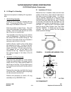
D. Servicing The Center Bearing (12 & 16
Cylinders)
The center bearing on this compressor is a split
sleeve type bearing much like connecting rod
bearings. To disassemble the bearing, remove
the four bolts holding the halves of the center