


February 2001
VILTER MANUFACTURING CORPORATION
SECTION 102-R
Replaces
PAGE 5
April 1984
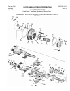
450 VMC COMPRESSORS
(High-Stage, Two-Stage, Booster and Heavy Duty)
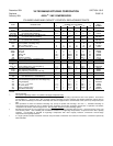
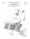
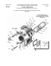
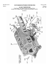
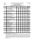
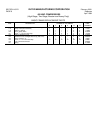
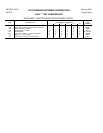
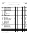
BASIC FRAME REPLACEMENT PARTS
QUANTITY REQUIRED PER COMPRESSOR
ITEM DESCRIPTION NUMBER OF CYLINDERS PART
2 4 6 8 12 16 NUMBER
101 Frame 1 1 1 1 1 1 +
102 Screw,
5
/
8
” x 3½” Hex Head Cap
(Used with Water Jacket)
20
40
60
80
120
160
13152L
102 Screw,
5
/
8
” x 2½” Hex Head Cap
(Used when Water Jacket not used)
20
40
60
80
120
160
13152G
103 Cover, Water Jacket (Ammonia and R22) 1 2 3 4 6 8 30299A
104 Gasket, Water Jacket (Ammonia and R22) 1 2 3 4 6 8 33329A
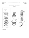
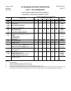
107 * Stud,
5
/
8
” x 3” (shown only on 2 Cylinder) 8 4 4 4 8 8 13156D
107 * Stud, ¾” x 3¼” (not shown) - - 4 4 4 - - - - 13157D
107 * Stud, ¾” x 3¾” - - - - - - - - 8 8 13157F
107-A * Nut,
5
/
8
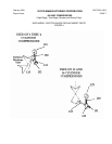
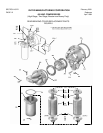
” Hexagon (see Figure 1) 8 4 4 4 8 8 1726G
107-A * Nut, ¾” Hexagon (see Figure 1) - - 4 4 4 - - - - 1726H
108 * Tee, Suction 2½” x 2½” (see Figure 1) 1 - - - - - - - - - - A30319A
108 * Tee, Suction 3½”x3” (not shown) - - 1 - - - - - - - - A32417B
108 †* Tee, Suction 5”x4” (not shown) - - - - - - 1 - - - - 36254C
108 †* Tee, Suction 4”x4” (not shown) (High Stage) - - - - 1 - - - - - - A36254B
108 †* Tee, Suction 4”x3” (not shown) (Booster) - - - - 1 - - - - - - A36254A
108 †* Tee, Suction 5”x4” (not shown) - - - - - - 1 - - - - A36254C
108 †* Elbow, Suction 4” (not shown) - - - - 1 - - - - - - 12273C
108-A * Gasket, 4” Flange (Suction/Discharge Conn) - - - - 2 2 - - - - 11323L
108-A * Gasket, 2½” Flange (Suction/Discharge Conn) 1 2 - - - - - - - - 11323H
108-A * Gasket, 3½” Flange (Suction/Discharge Conn) - - 1 - - - - - - - - 11323K
108-A * Gasket, 3” Flange (Suction/Discharge Conn) - - - - 3 - - - - - - 11323J
108-A * Gasket, 5” Flange (Suction/Discharge Conn) - - - - - - - - 1 1 11323M
108-B * Ring, Male Joint 4” (Suction) - - - - 1 - - - - - - 13151L
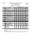
109 † Suction Screen 1 - - 2 2 - - - - A32428D
109 Suction Screen - - 1 - - - - - - - - A32428A
109 † Suction Screen (Center) - - - - - - 1 - - - - A32428C
109† Suction Screen (RH Side, 75% Cap Red) - - - - - - 1 - - - - A32428D
109 † Suction Screen - - - - 1 1 - - - - A35215A
109 Suction Screen - - - - - - - - 2 2 A32565A
109-A * Bag, Suction Screen (not shown) - - 1 - - - - - - - - A33474A
109-A †* Bag, Suction Screen (not shown) 1 - - 2 3 - - - - A33474B
109-A * Bag, Suction Screen (not shown) - - - - - - - - 2 2 A33474G
109-A †* Bag, Suction Screen (not shown) - - - - 1 1 - - - - A35234A
110 Gasket, Suction Screen Cover 1 - - 2 2 - - - - 31892A
110 Gasket, Suction Screen Cover - - - - - - - - 2 2 33493A
110 † Gasket, Suction Tee Cover - - 1 - - 1 - - - - 11323J
110 † Gasket, Suction Tee Cover - - - - 1 1 - - - - 35217A
111 Cover, Suction Screen 1 - - 2 2 - - - - 31893A
111 Cover, Suction Screen - - - - - - - - 2 2 33492A
111 † Cover, Suction Tee (VPN 32417 & 36254C) - - 1 - - 1 - - - - 13706A
111 † Cover, Suction Tee (VPN 36254) - - - - 1 1 - - - - 35216A
112 Screw,
5
/
8
” x 1½” Hex Head Cap - - 5 - - 5 - - - - 13152C
112 Screw,
5
/
8
” x 1¾” Hex Head Cap - - - - 6 6 - - - - 13152D
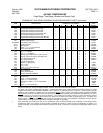
112 Screw, ½” x 1½” Hex Head Cap 6 - - 12 12 16 16 2796E
113 Valve, ½” Oil Charge and Drain 1 1 1 1 1 1 A15375A
113-A Nipple, ½”x4” Sch. 80 Pipe 1 1 1 1 1 1 13189G
114 Gasket, Crankcase Oil Screen 1 1 1 1 1 1 31889A
115 Crankcase Oil Screen Assembly 1 1 1 1 1 1 A31886A
116 Plug, ¾” Hex Head Pipe (not shown on 12) 1 1 1 1 1 1 13264E
116 Plug, ½” Hex Head Pipe (not shown on 2 thru 8) 1 1 1 1 1 1 13264D
NOTES:
* May not be shown, or only shown typically on one illustration.
+ Part Number on application
† 6 Cylinder Compressors with serial numbers below 45461 (oil unloading) and 60019 (gas unloading) are equipped with a suction
elbow and two suction screens (VPN A32428B) located behind the suction screen covers on the frame. 6 Cylinder compressors
with serial numbers 45461 (oil unloading) and 60019 (gas unloading) and above are equipped with a suction tee (VPN 36254) and a
single suction screen (VPN A35215A) located in the suction tee. 8 Cylinder compressors with serial numbers below 45461 (oil
unloading) and 60019 (gas unloading) are equipped with a suction tee (VPN 36254C) and three suction screens, one in the tee and
two behind the suction screen covers on the frame. 8 Cylinder compressors with serial numbers 45461 (oil unloading) and 60019
(gas unloading) and above are equipped with suction tee (VPN 36254) and a single suction screen (VPN A35215A) located in the
suction tee.
†† Part Number on application.