


VILTER MANUFACTURING CORPORATION
VILTER MultiCylinder Compressor
400 Series VMC 2/01
SERVICE - 18 - Replaces all Previous Issues
IX. OIL PUMP ASSEMBLY
NOTE:
Before proceeding, refer to Paragraph I, “General
Service Instructions”.
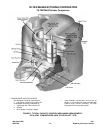
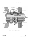
A. Removal
To remove the oil pump assembly, first remove
the filter tank and adapter from the rear housing.
Be prepared for a small amount of oil to drain
from adapter. The pump will be exposed in the
center and the outer pump housing will be cov-
ered by a gasket. Remove gasket. At the top
right and bottom left, you will find tapped holes to
aid in removing the pump, if necessary. The
pump housing is approximately 1½” (38.1 mm)
thick, so it requires jack screws 2” (50.8 mm) or
longer to release the inner gasket. Once loose,
pull the oil pump straight back.
The oil pump is a factory built and tested compo-
nent. It is furnished as a complete assembly only
and cannot be serviced in the field.
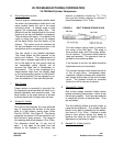
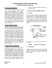
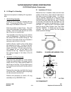
B. Replacement
To replace the oil pump assembly, first rotate the
crankshaft so the drive key is hanging from one
of four screws through the rear bearing retainer.
Make sure the small orifice plug in the rear hous-
ing (at the 12 o’clock position) is clear. Clean all
gasket surfaces. Install gasket (Vilter Part No.
31899A), correctly aligning oil passage holes.
Align pump shaft flats to match flats in pump
drive key. The locating dowel pin in the rear
housing should align with hole in the pump hous-
ing to the top-left-center.
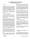
Install the pump and seat it against the inner
gasket. The outer surface of the pump should
now be recessed approximately
1
/
8
” (3.175 mm)
to the rear bearing housing. Install gasket (Vilter
Part No. 31900A), correctly aligning the holes.
The slot in this gasket should be at the 9 o’clock
position. Place the rubber seal gasket on the
filter adapter, and reattach the filter assembly
onto the rear housing. Install screws and tighten
down evenly.
X. PREPARATION FOR INTERNAL SERVICING
NOTE:
Before proceeding, refer to Paragraph I, “General
Service Instructions”.
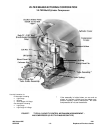
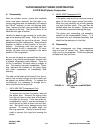
A. Handhole Cover Removal
To work internally on the compressor, the hand-
hole cover and crankcase oil will have to be re-
moved to gain access. The heater will have to
be electrically disconnected at this time. Re-
member to shut the power off and lock it out.
After disconnecting the wiring, loosen all but two
screws on the upper corners of the cover. This
helps support the cover during removal and pre-
vents damaging the heater. If the cover sticks to
the frame, a slight tap with a lead or soft face
hammer will free it.
Holding the cover in place, remove the two re-
maining screws, and pull the cover straight back
away from the frame. Remove any gasket mate-
rial from the cover and frame face. Also inspect
and remove any burrs or rough edges from the
mating surfaces to ensure a tight seal at time of
reassembly.
B. Handhole Cover Replacement
Lightly lubricate both sides of a new gasket with
refrigerant oil or general purpose grease. Place
the gasket on the cover, and guiding in the
heater, place the cover against the frame open-
ing. While holding the cover and making sure the
gasket is still in place, insert two screws in the
lower row to help support the cover and keep the
gasket from slipping out. Start the rest of the
screws in their holes and continue to check gas-
ket placement. Tighten screws evenly to the
torque requirements in Table 2, 3 or 4 (depend-
ing upon compressor model). Connect the
B. Handhole Cover Replacement (cont’d)