


February 2001
VILTER MANUFACTURING CORPORATION
SECTION 105-R
Replaces
PAGE 6
February 1985
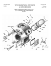
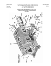
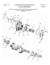
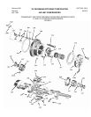
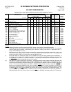
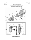
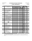
440 VMC COMPRESSORS
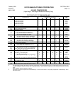
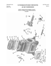
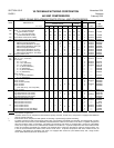
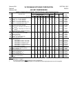
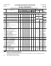
BASIC FRAME REPLACEMENT PARTS FOR ALL VMC COMPRESSORS
NO. REQ. PER COMPRESSOR SERIAL NO.
ITEM DESCRIPTION
SINGLE STAGE
TWO-
STAGE
PART
NO. OF CYL.
2 4 6 8 12 16 6 12 FROM THRU NUMBER
112 Screw,
5
/
8
” x 1½” Hex. Head Cap - - 5 - - 5 - - - - - - - - 0 * 13152C
112 Screw,
5
/
8
” x 1¾” Hex. Head Cap * - - - - 6 6 - - - - 6 - - * * 13152D
112 Screw, ½” x 1½” Hex. Head Cap 6 - - 12 12 - - - - 12 - - 0 Present 2796E
112 Screw, ½” x 1¼” Hex. Head Cap - - - - - - - - 16 16 - - 16 0 Present 2796EJ
113 Valve, ½” Oil Charge & Drain (Ammonia) 1 1 1 1 1 1 1 1 0 Present A15375A
113 Valve, ½” Oil Charge & Drain (Halo.) 1 1 1 1 1 1 1 1 0 Present 1956A
114 Gasket, Crankcase Oil Screen 1 1 1 1 1 1 1 1 0 Present 31889A
115 Crankcase Oil Screen Assembly 1 1 1 1 1 1 1 1 0 Present A31886A
116 Plug, ¾” Hex. Head Pipe (not shown on 12
& 16)
1 1 1 1 1 1 1 1 0 Present 13264E
116 Plug, ½” Hex. Head Pipe (not shown on 2
thru 8)
1 1 1 1 1 1 1 1 0 Present 13264D
117 Pin Retaining Assy, Crankcase Oil Screen 1 1 1 1 1 1 1 1 0 Present A31936A
118 Safety Valve (Internal Relief) 1 1 1 1 2 2 - - - - 0 Present 1721B
118A Valve, Crankcase Check (not shown) - - - - - - - - - - - - 2 2 - - - - - - A33568A **
119 Gasket, 2” Flange 1 1 1 1 2 2 - - - - 0 Present 11323G
120 Cover, Safety Valve 1 1 1 1 2 2 - - - - 0 Present 31954A
121 Screw,
5
/
8
” x 2” Hex. Head Cap 2 2 2 2 4 4 - - - - 0 Present 13152E
122 Gasket, Handhole Cover 1 1 1 1 2 2 1 2 0 Present 31894A
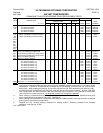
123 & Handhole Cover and 2” Sight Glass Assy
124A With openings for:
560W NEMA 1&7 Htr, F.V. & Therm 1 1 1 1 1 1 1 1 0 Present A33034G
300W NEMA 1&7 Htr, F.V. & Therm 1 1 1 1 1 1 1 1 0 Present A33034GA
560W NEMA 1&7 Heater & Therm 1 1 1 1 1 1 1 1 0 Present A33034L
300W NEMA 1&7 Heater & therm 1 1 1 1 1 1 1 1 0 Present A33034LA
560W NEMA 1&7 Heater & Float Valve 1 1 1 1 1 1 1 1 0 Present A33034G
560W NEMA 1&7 Heater 1 1 1 1 1 1 1 1 0 Present A33034L
123 Cover, Handhole (with openings) 1 1 1 1 1 1 1 1 0 Present Order Assy
123A Cover, Handhole (without openings) - - - - - - - - 1 1 - - 1 0 Present 33034B
124A Glass, Oil Sight – 2” 1 1 1 1 1 1 1 1 13050 Present 1484A
124 + Glass, Oil Sight – 3” 1 1 1 1 1 1 1 1 0 13049 31212A
125 + Washer, Oil Sight Glass – 3” 1 1 1 1 1 1 1 1 0 13049 31636A
126 + Lock, Oil Sight Glass – 3” 1 1 1 1 1 1 1 1 0 13049 31211A
127 + Gasket, Oil Sight Glass – 3” 2 2 2 2 2 2 2 2 0 13049 31226A
128 Screw, ½” x 1½” Hex. Head Cap 16 16 16 16 32 32 16 32 0 Present 2796E
130 Tube, Oil Feed Connector - - - - - - - - 1 1 - - 1 0 Present 33494A
131 Spring - - - - - - - - 1 1 - - 1 0 Present 31789A
NOTES:
* See Note ***, Page 5.
**. For use on compressors without external oil drain arrangement.
+ The crankcase cover for the 3” sight glass is not available, but these sight glass parts can still be supplied.