


SECTION 105-X
VILTER MANUFACTURING CORPORATION
February 2001
PAGE 4
Original Issue
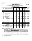
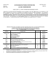
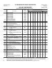
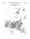
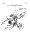
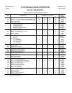
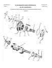
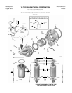
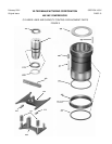
460 VMC COMPRESSORS
BASIC FRAME REPLACEMENT PARTS
QUANTITY REQUIRED PER COMPRESSOR
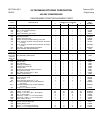
ITEM DESCRIPTION NUMBER OF CYLINDERS PART
2 4 6 8 NUMBER
101 Frame 1 1 1 1 *
102 Screw,
5
/
8
” x 2 ½” Hex. Head Cap (Used w/o Water Jacket) 20 40 60 80 13152G
102 Screw,
5
/
8
” x 3 ½” Hex. Head Cap (Used with Water Jacket) 20 40 60 80 13152L
103 Cover, Water Jacket 1 2 3 4 30299A
104 Gasket, Water Jacket 1 2 3 4 33329A
105 Cover, Cylinder
w/o Capacity Reduction - - 1 - - 2 A30332A
w/Capacity Reduction - - 1 - - 2 30332B
w/Capacity Reduction 1 - - 1 - - A30364A
Banks w/o Capacity Reduction 1 - - 1 - - A30364A
w/Capacity Reduction 1 - - 1 - - 30364B
106 Gasket, Cylinder Cover 1 2 3 4 33330A
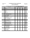
107 Stud,
5
/
8
” x 3” (shown only on 2 cylinder) 8 4 4 4 13156D
107 Stud, ¾” x 3¼” (not shown) - - 4 4 4 13157D
107A Nut,
5
/
8
-11NC-2B 1726G
107A Nut, ¾-10NC-2B - - 4 4 4 1726H
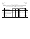
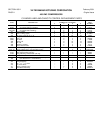
108 Tee, Suction (++)
2½” x 2½” 1 - - - - - - A30319A
3½” x 3” - - 1 - - - - A32417B
Elbow, Discharge (++)
2” x 2” (Ammonia) 1 - - - - - - 12270E
2½” x 2½” (Ammonia) - - 1 - - - - 12270F
3” x 3” (Ammonia) - - - - 1 - - 12271E
4” x 3” (Ammonia) - - - - - - 1 A32498A
109 Suction Screen 1 - - 2 2 A32428B
109 Suction Screen - - 1 - - - - A32428A
109 Suction Screen (Center) - - - - - - 1 A32428C
109 Suction Screen (R.H. Side, 8 cyl., 75% Cap. Red.) - - - - - - 1 A32428D
109-A Bag, Suction Screen (not shown) - - 1 - - - - A33474A
109-A Bag, Suction Screen (not shown) 1 - - 2 3 A33474B
109-A Bag, Suction Screen (not shown) - - - - 1 1 A35234A
110 Gasket, Suction Screen Cover 1 - - 2 2 31892A
110 Gasket, Suction Screen Cover - - 1 - - - - 11323J
110 Gasket, Suction Cover - - - - 1 1 35217A
111 Cover, Suction Screen 1 - - 2 2 31893A
111 Cover, Suction Screen - - 1 - - 1 13706A
111 Cover, Suction Screen - - - - 1 1 35216A
112 Screw,
5
/
8
” x 1½” Hex. Head Cap - - 5 - - 5 13152E
112 Screw,
5
/
8
” x 1¾” Hex. Head Cap 6 - - 12 12 13153E
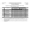
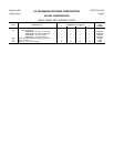
113 Valve, ½” Oil Charge and Drain (Ammonia) 1 1 1 1 A15375A
113 Valve, ½” Oil Charge and Drain (Halocarbon) 1 1 1 1 1956A
113A Nipple, ½” x 4” Sch. 80 Pipe 1 1 1 1 13189G
114 Gasket, Crankcase Oil Screen 1 1 1 1 31889A
115 Crankcase Oil Screen Assembly 1 1 1 1 A31886A
116 Plug, ½” Hex. Head Pipe 1 1 1 1 13264D
116 Plug, ¾” Hex. Head Pipe 1 1 1 1 13264E
117 Pin Retaining Assembly for Compressor Oil Screen 1 1 1 1 A31936A
118 Safety Valve, Internal Relief 1 1 1 1 1721B
119 Gasket, 2” Flange 1 1 1 1 11323G
120 Cover, Safety Valve 1 1 1 1 31954A
121 Screw,
5
/
8
” x 2” Hex. Head Cap 2 2 2 2 13152E
122 Gasket, Handhole Cover 1 1 1 1 31894A
NOTES:
* Part Number on application.