


VILTER MANUFACTURING CORPORATION
VILTER MultiCylinder Compressor
400 Series VMC 2/01
SERVICE - 4 - Replaces all Previous Issues
Lift off the washer, two diaphragm valves,
spacer and last diaphragm valve. Turn the
safety head assembly over and remove the
valve retaining screw. Remove the helical
suction valve springs from their sockets with
a twisting, pulling motion.
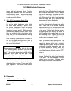
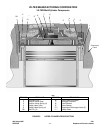
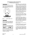
2. 450, 450XL Compressor (Bullet Style)
(See Figure 8)
Lift out the safety head yoke, which holds
the safety head assembly in place. Invert
the yoke to make sure all eight coil springs
are intact within it. If any springs are broken,
locate and remove pieces. Springs can be
removed and replaced without tools. Since
they are only finger tight in the bottom of the
hole, they can be removed with a twisting,
pulling motion.
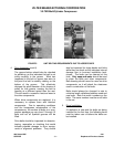
After the safety yoke has been removed, lift
out the ring plate discharge valve (refer to
note below). Slip the safety head up and off
the roll pin that guides it.
NOTE:
Before removing valve plates, look for the word
“TOP” etched on each plate and ring plate dis-
charge valve. This denotes the unlapped upper
face. If the etching is not clearly visible, dot the
upper face of the valve plate with dye or tape.
Do this sparingly. Any marking applied must be
removed prior to reassembly.
The safety head contains four helical suction
valve springs, which are identical to the eight
discharge valve springs. These need to be
kept separated. The suction valve can be
lifted out.
B. Reassembly
1. 440 Compressor (Mushroom Style)
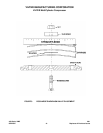
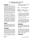
Before reassembling the safety head as-
sembly, the “top” of the discharge diaphragm
valve must be determined. Place a straight
edge on the diaphragms to reveal the dome.
Diaphragms are installed with the dome on
top. All pieces of the safety head assembly
should be clean and lightly lubricated with
compressor oil before reassembly.
To reassemble the safety head assembly,
insert the valve retaining screw in the safety
head. Place one of the domed discharge
diaphragm valves on the screw, making sure
the dome is up. Next, place the thin spacer
on the screw. Follow it with the two remain-
ing diaphragms, both having the dome on
top. Place the thicker washer and nut on the
valve retaining screw. Tighten the nut to the
torque value listed in Table 2, 3 or 4 (de-
pending upon compressor model).
Place the suction valve springs into the
holes with the end that has two coils wound
towards the bottom of the hole, and twist.
The springs lock in place. When the springs
are properly installed, the safety head can
be inverted without the springs falling out.
Place the suction valve plate in the cavity of
the cylinder liner with the side marked “TOP”
facing up.
Ensure the valve plate rotates freely, without
binding. Replace the safety head assembly
in the frame. Be sure no debris or foreign
material is on any parts. Replace safety
yoke on top of the safety head assembly.