


P—P28 and P128 Series Lube Oil Controls with Built-in Time Delay Relay Product/Technical Bulletin 3
Example: Net oil pressure (oil pump pressure minus
crankcase pressure) required to the
bearings is 9 psi (62 kPa). The control
scale setting should be 9 psi (62 kPa).
The switch differential is 5 psi (34 kPa).
Upon initial start of the compressor, the
time delay relay energizes. If the net oil
pressure does not build up to 14 psi
(97 kPa), or the scale setting (9 psi) plus
the switch differential (5 psi), during the
time delay, the control breaks the circuit to
the compressor. If the pressure of 14 psi
(97 kPa) is reached during the time delay,
the time delay relay de-energizes and the
compressor continues to operate normally.
I
nstallation
Mounting
!
CAUTION: Equipment damage hazard.
●
A P28AN or P28DN control used for
ammonia service must be mounted
separately from the electrical cabinet.
An ammonia leak could damage the
electrical circuitry.
●
Do not use Johnson Controls/Penn
Ecosafe® hose tubing in applications
with ammonia or other corrosive
refrigerants. Corrosion could cause
tube breakage and refrigerant
leakage.
●
Use only the mounting screws
supplied with the control. Damage to
internal components may occur if
other screws are used.
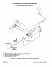
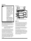
The P28 and P128 controls are not position sensitive
and can be mounted in any position.
Use the two mounting screw holes located on the
back of the control case to mount the control directly
to a wall or panel board. Mount the control so that
the pressure connections on the bellows are above
the crankcase liquid level of the equipment being
controlled.
Note: When mounting the control to a
compressor is required, a mounting bracket
(Part No. 271-51) is available.
Pressure Connections
!
CAUTION: Equipment damage hazard.
●
Avoid sharp bends or kinks in the
capillary or tubing to avoid damage to
the capillary.
●
Coil and secure excess capillary or
tubing. Because harmonic vibration
can break the capillary or tubing, some
slack must be provided.
●
Do not allow the capillary or tubing to
rub against metal surfaces where
friction can cause damage.
●
When using a control with
1/4 in. / 6.4 mm tubing, a pulsation
damper must be used. Pulsation can
cause excessive wear and damage
the control.
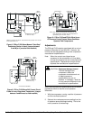
1. Purge all tubing and lines before connecting the
pressure control.
2. Connect the oil pressure line pump discharge to
the pressure connector labeled “OIL.”
3. Connect the crankcase pressure line to the
pressure connector labeled “LOW.”
4. Coil and secure excess capillary or tubing to
avoid vibration.
Wiring
!
WARNING:
Shock hazard.
Disconnect all
power supplies before making
wiring connections to avoid
electrical shock or damage to
the equipment.
●
Make all wiring connections using copper
conductors only.
●
Wire in accordance with National Electric Code
and local regulations. For maximum electrical
rating of the control, see the label inside the
control cover.
●
Use the terminal screws furnished (8-32 x 1/4 in.
binder head). Substitution of other screws may
cause faulty connections.