


P—P28 and P128 Series Lube Oil Controls with Built-in Time Delay Relay Product/Technical Bulletin 7
3. Set the cut-out pointer 6 to 8 psi (41 to 55 kPa)
below the established running net oil pressure with
the Adjusting Disk using a standard screwdriver.
To increase the cut-out pressure, turn the
Adjusting Disk counterclockwise. To decrease,
turn clockwise.
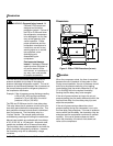
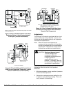
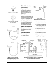
To raise the pressure differential, turn the
Adjusting Disk (see Figure 2) to the left when
viewing the front of the control. Turn the adjusting
disk to the right to lower the pressure differential.
T
est for Shutdown
Immediately after installing, and at regular intervals
thereafter, the time delay relay should be tested to
verify that all circuits are operating correctly.
!
WARNING: Shock hazard. Disconnect
power from the control before
testing for shutdown to avoid
electrical shock or damage to
the equipment.
To test for shutdown:
1. Remove power from the control and remove the
control cover.
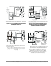
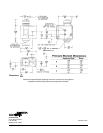
2. Connect a jumper between Terminals 1 and 2.
See Figure 3 for terminal locations.
Note: If the control is mounted on a condensing
unit where air from auxiliary equipment
(blowers or fans) may strike the control,
the control cover should be replaced
before proceeding to Step 3.
3. Apply power to start the compressor. The time
delay relay should trip after the time interval and
stop the compressor.
4. Remove power from the control and remove the
jumper between Terminals 1 and 2.
5. Replace the cover on the control and apply power.
6. Manually reset the time delay relay if required.
C
heckout Procedure
Before leaving the installation, observe at least
three complete operating cycles to be sure that all
components are functioning correctly.
F
ungus Proofing
Fungus proofing can be supplied at extra cost when
specified. Conforms to government specifications
MIL-V-173A.
R
epairs and Replacement
Field repairs must not be made, except for
replacement of the time delay relay assembly. For a
replacement control or time delay relay assembly,
contact the nearest Johnson Controls representative or
Refrigeration Application Engineering at 414-274-5535.
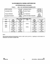
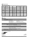
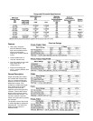
Table 3: Replacement Time Delay Relay Assemblies
Part Number Voltage Reset Type Timing in Seconds Alarm Circuit
RLY13A-600R
120/240 VAC Manual 60 No
RLY13A-602R
120/240 VAC Manual 90 No
RLY13A-603R
120/240 VAC Manual 90 Yes
RLY13A-608R
120/240 VAC Automatic 90 No
RLY13A-609R
24 VAC/VDC Manual 120 No
RLY13A-610R
120/240 VAC Manual 30 No
RLY13A-616R
120/240 VAC Manual 120 No
RLY13A-617R
120/240 VAC Manual 45 No