


VILTER MANUFACTURING CORPORATION
VILTER MultiCylinder Compressor
400 Series VMC 2/01
SERVICE - 10 - Replaces all Previous Issues
5. Drive Installation (cont’d)
The compressor, motor and base should be
level. This will help speed the alignment
process of the unit if the shafts are level and
in the same plane before starting the align-
ment process.
All piping must be finished and properly sup-
ported. Any piping stress must not be per-
mitted to act on the compressor frame. The
base must be secured to the floor and
grouted.
The compressor should be checked for a
soft foot and shimmed accordingly. Elimina-
tion of a soft foot in a belt drive compressor
is essential to reduce vibration and mis-
alignment problems.
The sheave and pulley should be checked
for paint and foreign matter in the grooves.
Any foreign material will cause a decrease in
the horsepower transmitting ability of the
belts and lead to accelerated wear of the
belts, pulley and sheave.
If this is an existing installation, the motor
and compressor shafts should be checked to
see if they are level and in the same plane
before starting the alignment process. If the
compressor has been moved or if there is a
complaint of excessive vibration, the com-
pressor should be checked for a soft foot.
Absolutely no lubricants or anti-seize com-
pounds should be used in the installation of
the motor sheave and bushing, or the crank-
shaft and flywheel. The bushing as supplied
by the manufacturer should not have any lu-
bricant applied to it or the sheave bore. The
applied lubricant will be trapped between
mating surfaces of the sheave and bushing,
or bushing and shaft. When the components
are tightened, the resulting hydraulic pres-
sure of the lubricant trapped between the
mating surfaces will result in a cracked
sheave or bushing. Lubricant or anti-seize is
usually applied to the shaft for ease of dis-
assembly. As the anti-seize is trapped when
the parts are tightened, it will create a sliding
layer between the parts. The parts are not
free to move independent of each other
while the unit is in operation, creating fretting
corrosion. This results in excessive wear of
the drive components and the possibility of
the parts welding themselves together.
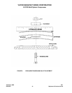
The belts can now be installed. The motor
should be moved towards the compressor to
facilitate the installation of the belts.
The belt closest to the compressor should be
installed first. The belts should not be rolled
or pried when installing them, as this will
damage the cords in the belts and cause a
failure in a short time.
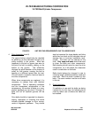
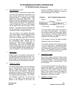
6. Drive Alignment
There are 3 different types of misalignment
that are possible, more than one of which
may be present at any one time. These are:
Horizontal angular
Vertical angular
Parallel
Although V-belt drives are somewhat tolerant
to misalignment, the maximum amount of
misalignment permitted is
1
/
16
of an inch per
12” of shaft, center to center distance. If this
is exceeded, excessive drive, belt and bear-
ing wear will result.
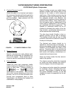
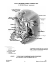
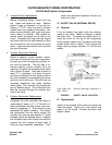
Horizontal angular misalignment results
when the motor and compressor shafts are
in the same horizontal plane, but not in the
same vertical plane. A straight edge is held
against the compressor pulley face. The dis-
tance from the straight edge to the motor
sheave sides is compared. They should be
the same. If they are not the same, adjust
the motor to bring the sheave and pulley into
alignment.