


VILTER MANUFACTURING CORPORATION
VILTER MultiCylinder Compressor
400 Series VMC 2/01
SERVICE - 8 - Replaces all Previous Issues
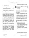
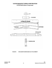
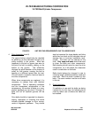
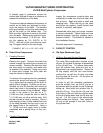
2. Flywheel Removal (cont’d)
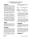
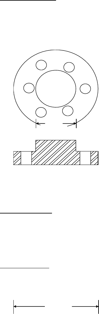
Screw the plate to the flywheel and tighten
the screws so the plate pulls tight against the
washers. Tighten the screws evenly so they
pull the flywheel. Apply pressure until the
flywheel breaks free.
FIGURE 4. FLYWHEEL REMOVAL TOOL
3. Sheave Removal
Specific instructions for motor sheave main-
tenance are located after the Operation Sec-
tion of this manual. These should be con-
sulted for specific maintenance instructions.
4. Drive Inspection
Inspect the motor and compressor shafts,
sheave bushing and flywheel for fretting cor-
rosion or other wear. Fretting corrosion is
the result of two metallic surfaces (a shaft
and flywheel or bushing bore) having move-
ment relative to one another. This is usually
due to the incorrect tightening of drive com-
ponents, use of oil or other anti-seize com-
pounds, worn components, burrs or other
imperfections not allowing the flywheel and
crankshaft to mate properly.
Signs of fretting corrosion are reddish brown
powdery oxidation and wearing away of the
surface of the shafts or drive component
shaft bores. Minor fretting corrosion may be
eliminated through light sanding after which
the adequate contact area between the
crankshaft and flywheel must be assured to
prevent further fretting. Heavy fretting corro-
sion will require repair or replacement of the
motor shaft or replacement of the compres-
sor crankshaft and drive components. The
flywheel or crankshaft should not be re-
matched to eliminate the results of the fret-
ting corrosion, as adequate clearances can-
not be assured after remachining.
The drive keys should fit tightly in their re-
spective grooves and be free of damage.
The keyways should also be free of chips
and burrs that would not allow full contact of
the key to the keyway.
The flywheel and sheave should be in-
spected for abnormal wear and damage. A
groove wear gauge should be used to check
condition of the sidewalls and width of the
groove. Excessive wear is not permitted as
this will lead to problems in achieving correct
belt tension and loading, contributing to ex-
cessive belt and sheave wear.
Clean any foreign matter that has accumu-
lated in the grooves.
The sheave and pulley should be inspected
for cracks and other damage that could af-
fect the integrity of the drive components.
The sheave and pulley should be inspected
for excessive run-out, indicating bent com-
ponents. Bent pulleys or sheaves will wear
the groove sidewalls unevenly, as the belt
changes its angle of engagement as the pul-
ley turns.
5
”
Dia.
2
”
Dia.