


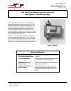
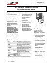
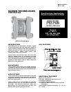
8 P—P28 and P128 Series Lube Oil Controls with Built-in Time Delay Relay Product/Technical Bulletin
O
rdering Information
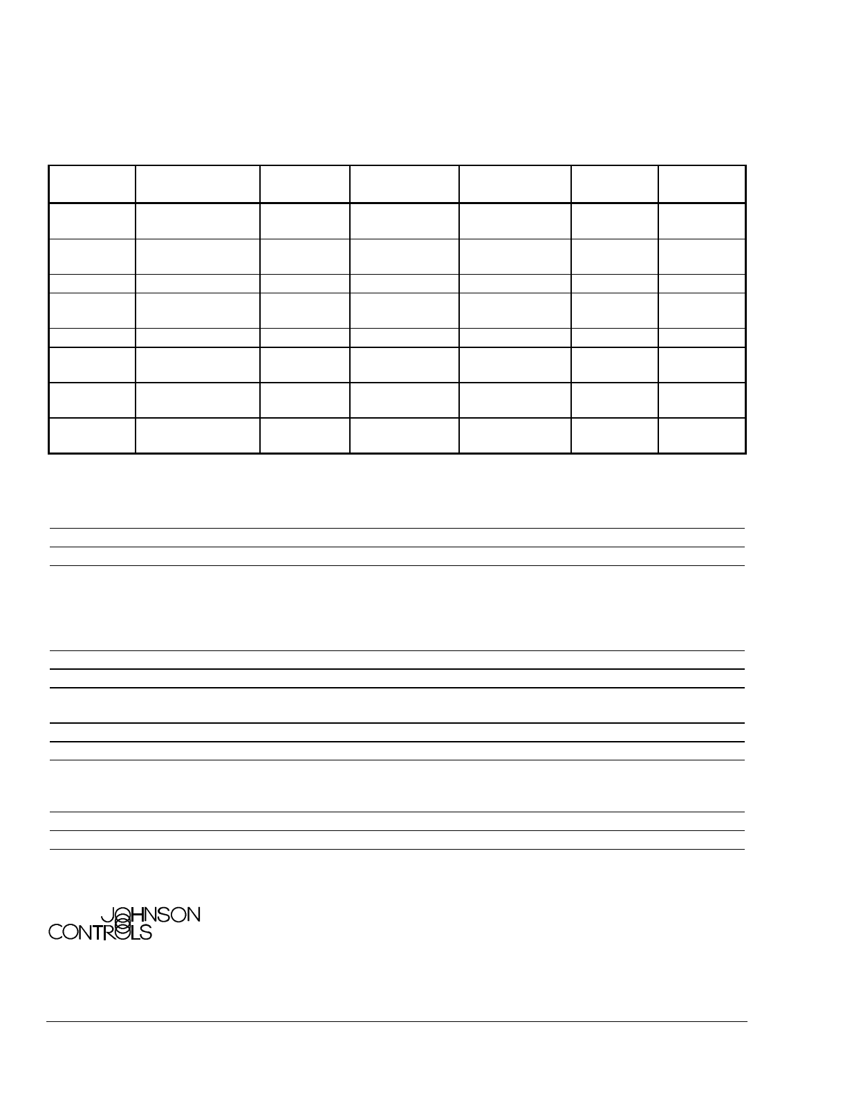
Table 4: Ordering Information
Series Part
Number
Pressure
Connections*
Reset Type Refrigerant Time Delay
Relay Voltage
Alarm
Terminal
Runlight
Terminal
P28AA
Style 13, Style 5,
or Style 15
Manual Non-corrosive
All-range
120/240 VAC No No
P128AA
Style 5 Manual Non-corrosive
All-range
120/240 VAC No No
P28AN
Style 15 Manual Ammonia 120/240 VAC No No
P28DA
Style 13 Manual Non-corrosive
All-range
120/240 VAC Yes Yes
P28DN
Style 15 Manual Ammonia 120/240 VAC Yes Yes
P28GA
Style 13 Automatic Non-corrosive
All-range
120/240 VAC No No
P28NA
Style 13 or Style 5 Manual Non-corrosive
All-range
24 VAC/VDC No No
P28PA
Style 5 Manual Non-corrosive
All-range
24 VAC/VDC No No
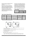
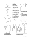
* Style 5 connections are 1/4 in. / 6.4 mm SAE male flare connectors (no capillary tubing). Style 13 connections are 36 in. / 914 mm
capillary tubing and 1/4 in. / 6.4 mm flare nut. Style 15 connections are 1/4 in. / 6.4 mm female National Pipe Thread connectors.
S
pecifications
Product
P28 and P128 Series Lube Oil Controls with Built-in Time Delay Relay
Power Requirements
See Tables 1 and 2.
Pressure Specifications
Adjustable Cut-out Pressure Difference: 8 to 70 psi (55 to 483 kPa)*
Maximum Differential: 70 psi (483 kPa)
Maximum Working Pressure: 250 psig (1724 kPa) on the high side
Maximum Overpressure: 325 psi (2240 kPa) oil and low side pressure
*The time delay relay is de-energized 3 to 5 psi (21 to 34 kPa) above the cut-out scale setting.
Pressure Switch Units
Enclosed Dust-protected Pennswitch
Ambient Operating Conditions
32 to 104
°
F / 0 to 40
°
C
Material
Case: 0.062 in. / 1.6 mm Galvanized Steel
Cover: 0.028 in. / 0.7 mm Cold Rolled Steel (plated and painted)
Mounting
Flat Surface or with a Universal Mounting Bracket (Part No. 271-51)
Wiring Terminal
Large 8-32 x 1/4 in. Binder Head Screws
Agency Listings
UL Guide No. SDFY; File SA516**
CSA Class No. 1222 01; File LR948**
*
*Most models. Contact Johnson Controls for a complete listing.
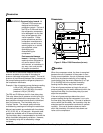
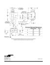
Dimensions (H x W x D)
5.66 x 5.32 x 2.09 in. / 144 x 135 x 53 mm
Shipping Weight
3.0 lb / 1.36 kg
The performance specifications are nominal and conform to acceptable industry standards. For application at conditions beyond these specifications,
consult the local Johnson Controls Refrigeration Application Engineering at (414) 274-5535. Johnson Controls, Inc. shall not be liable for damages
resulting from misapplication or misuse of its products.
Controls Group FAN 125
507 E. Michigan Street Master Catalog
P.O. Box 423 Printed in U.S.A.
Milwaukee, WI 53201