


VILTER MANUFACTURING CORPORATION
VILTER MultiCylinder Compressor
400 Series VMC 2/01
SERVICE - 7 - Replaces all Previous Issues
1. 440 Compressor (Mushroom Style) (cont’d)
All replacement parts are drilled. They are
interchangeable with original parts. All re-
placement cylinder line kits have roll pins.
Discard roll pins if new liner is being used
with old safety head and safety head yoke.
The old style frames have built-in guide lugs
which serve the same purpose as the roll
pins. Replace safety springs and cylinder
covers on the compressor.
NOTE:
Compressors with serial numbers 7000 and
higher have 4 holes drilled through the safety
head and safety head yoke into the cylinder liner,
to accommodate roll pins.
After replacing the cylinder cover, return the
unloader mechanism to its operating position
by removing the metal rod from the hole in
the frame. This allows the piston to rise.
Put the plug back into the hole (hole ‘B’) in
the frame and reconnect the unloader lines.
2. 450, 450XL Compressor (Bullet Style)
Before assembling the valves, safety head
and yoke, use a solvent to remove any dye,
paint or tape you may have used as a
marker.
Put the suction valve into their holes with the
end that has two coils closely wound to-
wards the bottom of the hole and twist with
the top of the finger. This will lock the spring
in its hole. The springs are properly installed
when the safety head can be inverted with-
out the springs falling out. Springs of all the
same “hand” are used (wound the same
way). This allows the valve to rotate during
operation. When the valve rotates, the ac-
tion tends to “heal” any small nicks or
scratches on the valve or seal, and clean
away any foreign material or dirt which may
lodge between the valve and seat. This will
also spread out the plate wear from the
springs.
Place the suction valve into its cavity in the
cylinder liner with the “top” facing up. The
valve plate should rotate freely without bind-
ing. Replace the safety head assembly in
the frame.
IV. COMPRESSOR DRIVE TYPES
NOTE:
Before proceeding, refer to Paragraph I, “General
Service Instructions”.
A. V-Belt Drive Compressors
1. Belt Removal
Remove belt guard.
Loosen motor rail clamps. Remove tension
on belts to provide enough slack to allow the
belts to be removed from the drive without
having to pry or roll the belts off.
If belts are to be reused, mark the belts to
orientation on the drive. The belts can now
be removed.
2. Flywheel Removal
Remove flywheel screw holding the flywheel
on the shaft.
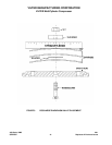
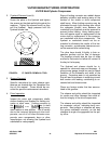
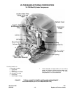
Install flywheel puller on the flywheel. An al-
ternate tool can be fabricated from a 4½”
(107.95 mm) diameter steel plate, ½” (12.7
mm) thick with three equally spaced
11
/
16
”
(17.46 mm) holes on a 3½” (82.55 mm) or
3
7
/
8
” (98.43 mm) bolt circuit. See Figure 4.
Also needed are several 1¾” (44.45 mm)
plate washers and three
5
/
8
” (15.88 mm) x
1¾” (44.45 mm) long screws. Place several
washers against the end of the shaft so they
extend past the flywheel hub.