


December 2001
VILTER MANUFACTURING CORPORATION
SECTION 100-R
Replaces
PAGE 15
February 2001
450XL
®
* VMC COMPRESSORS
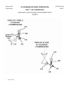
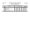
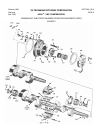
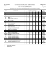
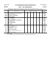
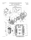
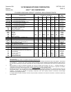
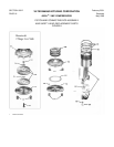
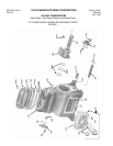
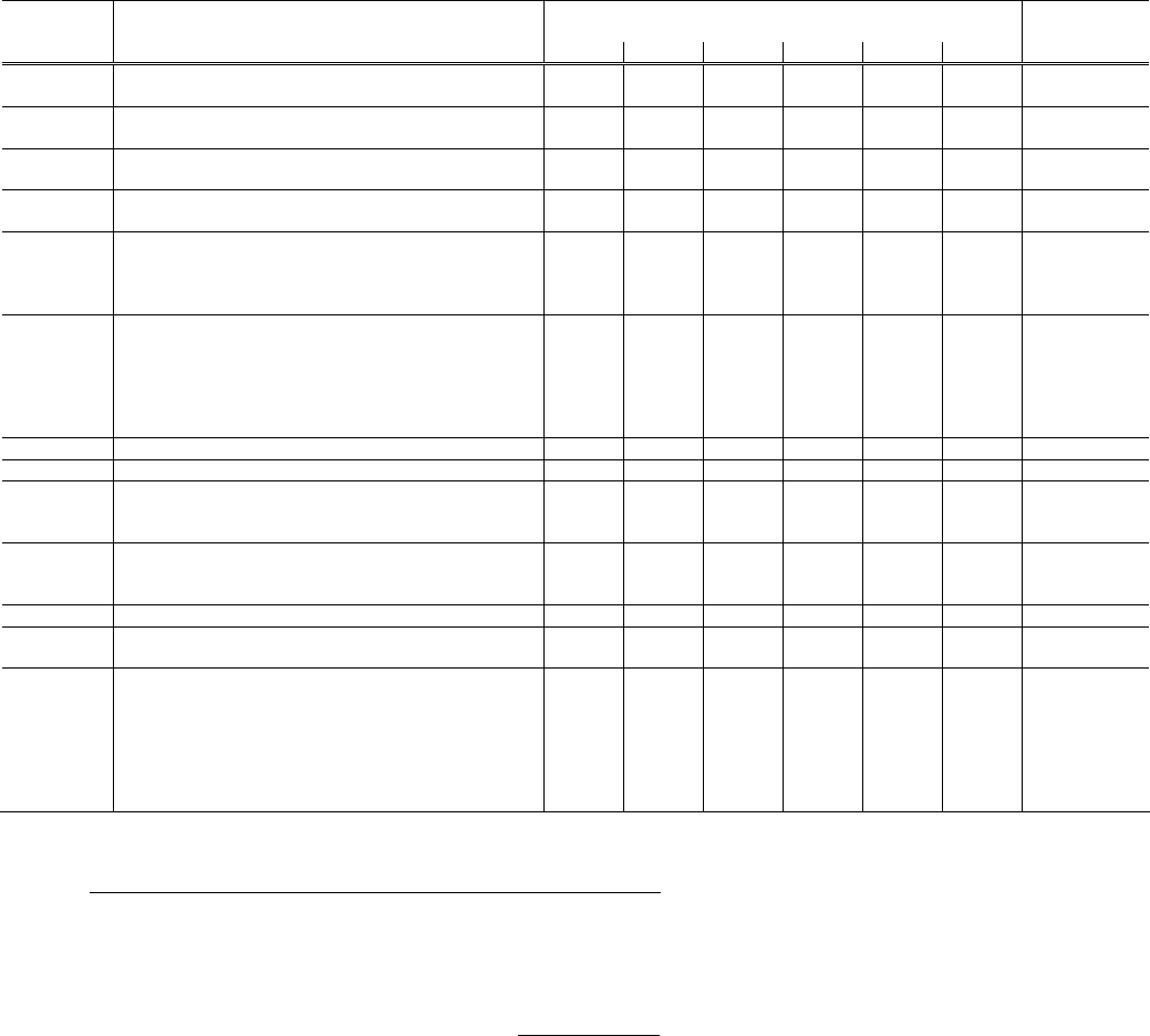
CYLINDER LINER AND CAPACITY CONTROL REPLACEMENT PARTS
QUANTITY REQUIRED PER COMPRESSOR
ITEM DESCRIPTION NUMBER OF CYLINDERS PART
2 4 6 8 12 16 NUMBER
401, 402 Cylinder Liner Assembly
& 403 (for cylinder without unloading) 2(1**) 2 2 4 4 8 KT475
401, 402 Cylinder Liner Assembly
Thru 408 (for cylinder with unloading) -(1**) 2 4 4 8 8 KT476
401A, 402, Cylinder Liner Assembly (Two-Stage only)
403 & 408A (for cylinder without unloading) - - - - 6(3**) - - 12(6**) - - A35108D
401A, 402 Cylinder Liner Assembly (Two-Stage only)
Thru 408A (for cylinder with unloading) - - - - -(3**) - - -(6**) - - A35108C
401 Liner, Cylinder 2 4 6 8 12 16 34510A
401A Liner, Cylinder (Two-Stage only) - - - - 6 - - 12 - - 34710A
402 Seal, ‘O’ Ring (upper) 2 4 6 8 12 16 2176BH
403 Pin, Roll, 0.125” dia. x 1½” lg. 8 16 24 32 48 64 1193Q
405 Ring, Lift -(1**) 2 4(3**) 4 8(6**) 8 35071A
405A + Ring, Lift 1 2 4 4 8 8 35380A
405B + Pin, Roll 4 4 4 4 4 4 1193SS
406 Spring, Lift -(8**) 16 32(24**) 32 64(48**) 64 35069A
407 Pin, Lift -(8**) 16` 32(24**) 32 64(48**) 64 35070A
408 Retainer, Lift Ring -(1**) 2 4(3**) 4 8(6***) 8 1971A
408A Seal, ‘O’ Ring (lower – Two-Stage only) - - - - 6 - - 12 - - 2176BL
409 Plate, Suction Valve 2 4 6 8 12 16 31909A
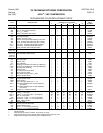
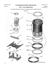
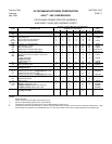
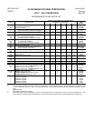
410A/B &
411
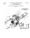
Piston & Rings Assy., Cap Red (Oil †) -(1**) 1 2(3**) 2 4(6**) 4 A35315BX
410 & 411 Piston & Rings Assy., Cap Red (Gas †) -(1**) 1 2(3**) 2 4(6**) 4 A35315CX
410 Ring Set (PTFE & rubber) -(1**) 1 2(3**) 2 4(6**) 4 2557A
410A Seal, Unload Piston (Oil only) 1 1 1 1 1 1 2639A
410B Ring, Retaining Unload Piston (Oil only) 1 1 1 1 1 1 2638A
411 Piston, Unloader (Gas or Oil) -(1**) 1 2(3**) 2 4(6**) 4 Order Assy
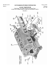
413 thru Complete Capacity Control Mechanism Assembly * - - 1 2 2 4 4 A41788BX
420 (Low Suction R717 and all Booster)
413 Arm, Yoke Lifting -(1**) 1 2(3**) 2 4(6**) 4 41725A
414 Yoke Assembly (2 Cylinder and Two-Stage only) -(1**) - - -(3**) - - -(6**) - - A33575A
414 Yoke Assembly - - 1 2 2 4 4 A33335A
415 Pin,
3
/
8
” x
11
/
16
” lg. Roll -(1**) 1 2(3**) 2 4(6**) 4 1193X
416 Pin, Short Pivot -(1**) 1 2(3**) 2 4(6**) 4 33250B
417 Spring, Unloader Yoke -(4**) 4 8(12**) 8 16(24**) 16 33686A
418 Yoke Guide Assembly - - 1 2 2 4 4 A33347A
NOTES:
* Patents Pending.
** Two cylinder high stage and 6 & 12 cylinder Two-Stage Compressor only
:
Unloading is NOT standard. When supplied as an option, single cylinder unloading is provided on 50% of the cylinders. These items
and quantities in ( ) are then used. Also, for single cylinder unloading, the yoke assembly (Part Number A33575A) and two pins on
the Yoke Guide Assembly (Part Number A33576A) have drill and tapped holes to accommodate screw (Item 419) and spacers (Item
420).
*** Parts quantities are listed for standard unloading only (except 2 cylinder and two-stage, see note **). Standard unloading on
compressors with 2 cylinders is none; 4 cylinders is 50%; 6 cylinders is 33 & 66%; 8 cylinders is 25 & 50%; 12 cylinders is 33 & 66%;
16 cylinders is 25 & 50%; and two-stage is none. See Operation Section
for other unloading options.
† Actuation type presently on your compressor can be determined by checking unloading solenoid valve – oil uses three-way valves, gas
uses two-way valves. Gas unloading was considered standard on all high-stage compressors, except those with 100% capacity
reduction. Oil unloading is standard on high-stage compressors with 100% capacity reduction, all boosters and two-stage
compressors with capacity reduction.
+ If a single cylinder unloader mechanism serviced uses pivot bolts to hold down one half them mechanism, it should be replaced by
405A and 405B.