


VILTER MANUFACTURING CORPORATION
VILTER MultiCylinder Compressor
400 Series VMC 2/01
SERVICE - 2 - Replaces all Previous Issues
3. Compressor Oil Removal
If service will be performed on unloader so-
lenoids, oil filter change, suction or dis-
charge valves, or crankshaft seal, the oil will
not require removal. If it becomes necessary
to open the crankcase, disconnect power to
the heater and remove oil through the drain
valve.
If a slight positive pressure is allowed to re-
main in the crankcase before compressor is
opened, it will force the oil from the drain
valve into a container of sufficient capacity.
It is best to have reduced the pressure to 2
psig (13.79 kPa) to minimize the amount of
foaming.
After the compressor has been serviced, do
not reuse this oil. Even reconditioned oil
contains contaminates that could cause
compressor damage.
C. Preparation Of Compressor For Initial
Start After Servicing
Vilter recommends charging 1 to 2 gallons of
fresh oil into the compressor via the oil pressure
gauge port in the front housing. This eliminates
“dry start-up” by forcing oil into the passageways
in the crankshaft, to the connecting rods, and
having a good supply of oil for the shaft seal.
Add oil to crankcase, via drain valve, to within 1/2
of the sight glass in the handhole cover. Connect
power to the crankcase heater, close all open
valves, and check for leaks.
When oil has reached approximately 100°F
(37.8°C), start the compressor and allow it to pull
the load down gradually. Run the compressor for
a few minutes, then stop for a cooling off period.
Restart and run for a longer time. Stop and allow
for a cooling off period again.
Lengthen each running period until it is deter-
mined no moving parts are heating up exces-
sively.
When the compressor operates with normal run-
ning temperatures, allow it to run for whatever
length of time the load requires. With new or re-
placement compressors, the suction bag should
be removed after running for 24 hours.
II. CYLINDER COVERS
NOTE:
Before proceeding, refer to Paragraph I, “General
Service Instructions”.
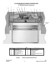
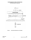
A. Disassembly
To remove the compressor cylinder covers, re-
move the capacity control lines and water lines
(or liquid cooling lines, if any) from the covers
that will be removed. Next, remove two screws
that are opposite each other diagonally across
the cover (i.e. two screws by water connections).
Install two assembly studs into these holes and
tighten them to thread bottom. Screw on nuts to
within one thread of touching the cover. Remove
the other screws. Slowly back the two nuts off
and make sure the cover follows.
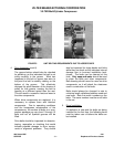
If the cover doesn’t follow, STOP. DO NOT
back off nuts more than one turn. Break the gas-
ket seal and then continue cover removal.
The studs are long enough to relieve all the
spring tension before the nuts are removed.
Remember, the studs must not be turned out with
the nuts. After all of the spring tension is re-
moved, the nuts can be removed, covers lifted off
and head springs removed. It is best to keep all
parts in the correct cylinder assignment. Invert
the cover and place on work surface, placing
each spring in its corresponding location in the
cover.