


February 2001
VILTER MANUFACTURING CORPORATION
SECTION 102-R
Replaces
PAGE 11
April 1984
450 VMC COMPRESSORS
(High-Stage, Two-Stage, Booster and Heavy Duty)
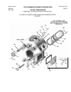
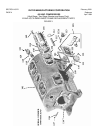
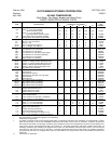
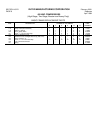
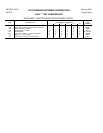
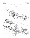
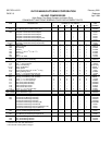
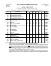
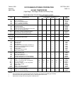
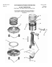
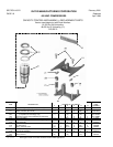
CRANKSHAFT AND FRONT BEARING COVER REPLACEMENT PARTS (continued)
QUANTITY REQUIRED PER COMPRESSOR
ITEM DESCRIPTION NUMBER OF CYLINDERS PART
2 4 6 8 12 16 NUMBER
229 Crankshaft & Retaining Compound Kit 1 - - - - - - - - - - KT377
229 Crankshaft & Retaining Compound Kit - - 1 - - - - - - - - KT378
229 Crankshaft & Retaining Compound Kit - - - - 1 - - - - - - KT379
229 Crankshaft & Retaining Compound Kit - - - - - - 1 - - - - KT380
229 Crankshaft & Retaining Compound Kit (HD) - - - - - - 1 - - - - KT559
229 Crankshaft & Retaining Compound Kit - - - - - - - - 1 - - KT381
229 Crankshaft & Retaining Compound Kit (H/S HD) - - - - - - - - - - 1 KT560
229 Crankshaft & Retaining Compound Kit (Booster) - - - - - - - - - - 1 KT561
229-A Plug, Pipe,
1
/
8
”, Hex Socket Head (not shown) 5 5 5 5 8 8 13163A
231 Retainer, Rear Bearing 1 1 1 1 1 1 31904A
231A&231B Rear Bearing and Lock Pin Kit 1 1 1 1 1 1 KT353
231-A Pin, Bearing Lock 1 1 1 1 1 1 33678A
231-B Bearing, Rear 1 1 1 1 1 1 A33509A
232 Screw,
5
/
16
” x 1½” Hex Head Cap 4 4 4 4 4 4 1736G
233 Crank, Oil Pump Drive 1 1 1 1 1 1 33403A
234 Cap, Bearing Support - - - - - - - - 1 1 *
235 Pin, ¼” x 1” Dowel - - - - - - - - 2 2 13162X *
236 Bolt, ½” x 1¾” Machine - - - - - - - - 4 4 2796EL
237 Bearing, Upper Right Half or Lower Left Half - - - - - - - - 2 2 33508A
238 Bearing, Upper Left Half or Lower Right Half - - - - - - - - 2 2 33508B
239 † Dam, Center Bearing Oil - - - - - - - - 2 2 33498A †
240 Pin, Threaded Taper - - - - - - - - 1 1 33497A
241 Case, Bearing Support - - - - - - - - 1 1 *
242 Washer, ½” Spring Lock - - - - - - - - 4 4 13165F
243 Nut, ½” Hex - - - - - - - - 4 4 1726E
244 Nut,
9
/
16
” Hex - - - - - - - - 1 1 13253F
245† Screw, ¼” x ½” Hex Head Cap - - - - - - - - 8 8 2796AC †
246 Key, Crankshaft 1 1 - - - - - - - - 31994B
246 Key, Crankshaft - - - - 1 1 1 1 33505B
247 Screw, Flywheel Hub 1 1 1 1 1 1 31956A
248 Washer, Flywheel Hub Screw - - - - 1 1 1 1 33495A
249 Gauge, Oil Pressure, 300 PSI 1 1 1 1 1 1 1204E
250 Stedy-Mount
®
1 1 1 1 1 1 A17311SS
251 Valve, ¼” Screw End Globe 1 1 1 1 1 1 A11392A
252 Nipple, ¼” x 7” Sch. 80 Pipe 1 1 1 1 1 1 13181M
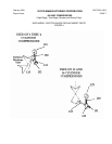
253 Connector, ¼” MPT x ¼” O.D. Compression 1 1 1 1 1 1 13229D
254 Tee, ¼” 1 1 1 1 1 1 1098B
255 Nipple, ¼” x 2” Sch. 80 Pipe 1 1 1 1 1 1 13181C
NOTES:
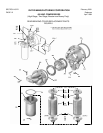
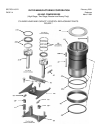
* Matched set with pins, sold as assembly A32163A. Shown in three parts to illustrate disassembly.
+ See Page 8 for symbol regarding this information. Compressors below serial number 45330 were furnished with the no longer
available front bearing cover assemblies A30294A (2 and 4 cylinders) or A32162A (6,8 and 12 cylinders), and front bearing retainer
31885A (2 and 4 cylinders) or 33500A (6, 8 and 12 cylinders) without
oil hole. Former front bearing retainers (31885A or 33500A)
without
oil holes cannot be used with current front bearing cover assemblies A36240A (2 and 4 cylinders) and A36241A (6, 8 and 12
cylinders), as there is no way for oil to get to the bearing. If front bearing cover is being replaced, a current front bearing retainer
(31885A or 33500A with
oil hole) must be ordered also, unless one of these current styles is already being used. If a current front
bearing retainer, (31885A or 33500A, both with oil hole) is used with former style cover (A30294A or A32162A) having an oil hole,
remove orifice in cover (A30294A or A32162A) and replace with solid 1/8” pipe plug.
† Dams (Item 239) and screws (Item 245) are not needed when using VILTER’s patented joined crankshafts. In this design version
(introduced in 1980), two 6 cylinder or two 8 cylinder crankshafts are joined by a sleeve to form an inseparable 12 cylinder or 16
cylinder crankshaft. This specially machined sleeve eliminates the dams. This design is completely interchangeable with the former
design.