


VILTER MANUFACTURING CORPORATION
VILTER MultiCylinder Compressor
400 Series VMC 2/01
SERVICE - 24 - Replaces all Previous Issues
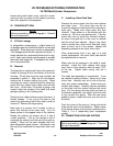
B. Lift Rings For Unloading
There are two styles of unloading lift ring assem-
blies.
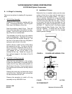
1. 440 Lift Ring Assembly
Rotate the lift to align the notches with the
pins. The springs will follow. The lift ring will
then drop to the bottom of the liner.
Note the position of each lift pin. They will
have to be returned to that position for reas-
sembly. Push the lift pins up and out of the
top of the liner to remove them.
The assembly of the lift ring is the reverse
order of disassembly. Place the lift ring on a
flat surface with the notches facing up. Put
the liner in the center of the ring, and place a
spring on each roll pin in the ring.
Install a lift pin in each of the 4 slots along
the outside of the liner. The flat on the bot-
tom of the lift pin should be flush to the di-
ameter of the liner. Lift the ring up the liner,
and engage all four lift pin slots in the
notches on the ring. Rotate the ring so the
four springs engage in the holes of the lift
ring stop.
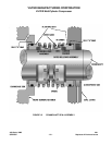
2. 450/450XL Lift Ring Assembly
Invert the liner and place on a flat surface.
Locate the notched end of the snap ring that
retains the lift ring, while pushing down on
the lift ring in this area. Pry the snap ring out
of its groove and continue all the way around
the liner.
Remove the snap ring, and slide the ring up
and off the liner. Now the 8 pins and springs
can be removed from the liner.
Reverse the procedure to install a lift ring
assembly on any 450/450XL liner.
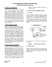
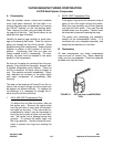
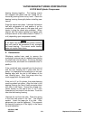
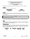
B. Installation Of Liners
Before the liner is installed, make sure the outer
surface of the liner is clean and the seat area in
the frame is free of foreign matter. If a new o-
ring is required, lubricate the o-ring and frame
seating area with refrigeration oil. Slide the liner
into the frame and align with the bore. Roll pin
on the top of the liner can be orientated so if an
imaginary line is drawn to opposite pins, it forms
the letter “X”. Seat the liner in the frame recess
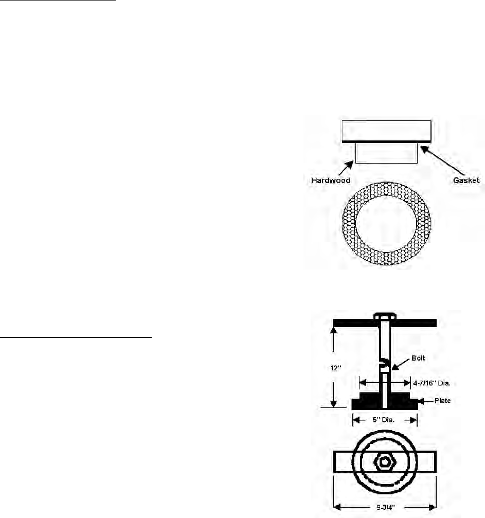
firmly by use of Vilter Cylinder Liner Tool (Vilter
Part No. 33464A). A similar tool can be con-
structed. Be sure to protect the liner lapped
seats to prevent damage.
FIGURE 14. CYLINDER LINER ASSEMBLY TOOL
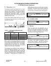
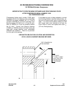
FIGURE 15. CYLINDER LINER REMOVAL TOOL
XIV. CRANKSHAFT