


Programming with a Series 200/300 Computer
103
B
Programming With a Series 200/300 Computer
Introduction
The purpose of this appendix is to serve as an introduction to programming your power supply with an HP Series 200/300
computer using the BASIC language. Examples are included that employ some of the most frequently used functions.
These examples have been written so that they will run on all power supplies. The values used in the examples (5 V and 0.5
A for instance), are within the operating locus of all outputs on all models. The examples program only channels one and
two because both models contain at least two channels (outputs).
You must be familiar with the BASIC language to understand the examples. If you do not recognize a programming
statement, look up the keyword in the BASIC Language Reference document that was supplied with your computer, and
look up the device command in Chapter 5 of this manual. Questions about program structure and selection are discussed in
the BASIC Programming Techniques manual.
I/O Path Names
Throughout this appendix, I/O path names are used in place of interface and device select codes. In a large program, I/O
path names simplify changing the address of an instrument if necessary. Reading and writing the program is easier as well.
The I/O path name can be carried in a common block and changed by a single assign statement.
In the programming examples in this appendix, the I/O path name @Ps is used for the power supply. The ASSIGN
statement that defines the I/O path must precede any statements that use the I/O path name. Therefore, instead of using the
statement OUTPUT 705;’’VSET1,5’’ in the following programs, the equivalent OUTPUT @Ps;"VSET1,5" statement is
used. The examples assume that the power supply is at address 5 and the GP-IB interface in the computer is at select code
7(factory default).
Voltage and Current Programming
The power supply normally functions in one of two modes, either constant voltage with current limit or constant current
with voltage limit. The operating mode is determined by a combination of voltage and current settings and load resistance.
For example, with a 50
Ω
load connected to output 1, the following program will put output 1 in constant voltage mode at 5
volts out with a 0.5 amp current limit. In this case the output current would be 0.1 A.
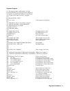
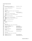
10 ASSIGN @Ps TO 705
20 OUTPUT @Ps;’’VSET1,5;ISET1,0.5’’
30 END
Line 10: Assigns the I/O pathname to the power supply.
Line 20: Sets output voltage and current. Note the use of the semicolon to separate multiple device commands.
If a 4 Ω load were used instead of a 50 Ω load, output 1 would have been operating in constant current mode at 0.5 amp out
with a voltage limit of 5 volts. In this case the output voltage would be 2 V.