


Command Summary
114
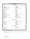
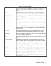
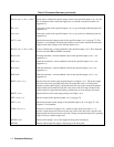
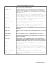
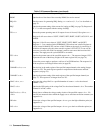
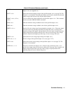
Table C-2 Command Summary (continued)
ROM? Queries the revision date of the power supply’s firmware. See service manual.
SROM? Queries the revision date of the secondary ROM. See service manual.
SRQ <X> Sets the causes for generating SRQ. Setting < x > can be a 0, 1, 2, or 3 as described on
page 79.
SRQ? Queries the present setting of the reasons for issuing an SRQ (see page 79). Response is
0, 1, 2, or that corresponds with the settings for SRQ.
STO < x > Stores the present operating state of all outputs in one of eleven (0-10) registers < x > .
Register 0 will store values of: VSET, VRSET, ISET, IRSET, OVSET, OCP, DLY, and
MASK.
Registers 1-10 will store values of: VSET, VRSET, ISET, IRSET, and OVSET.
Registers 1 - 3 are contained in the EEPROM (U230) and are non-volatile. Registers 6-
10 are located in RAM (U207) and are volatile. Whenever the supply is powered up, it
initializes all outputs using the values stored in register 0. STO <0,1,2,3> can only be
sent once. An error will result if an attempt is made to store more than once into each
location. The supply must be cycled ON/OFF to re-enable.
STS? < ch > Queries the present status of the specified output < ch > . The response (integer 0-255)
represents the sum of the binary weights of the status register bits (see page 76).
TEST? Causes the power supply to perform a self test of its GP-IB interface. The response is 0
if the test passes or an integer failure code (see page 82).
UNMASK < ch >, < x > Sets the bits in the mask register of the specified output channel to the setting (integer
from 0 to 255). The mask register operates in conjunction with the status and fault
registers (see page 78).
UNMASK? < ch > Queries the present setting of the mask register of the specified output channel (see
page 77). The response is an integer from 0 to 255.
VDAC < ch >, < x > Programs the voltage DAC to a specified number of counts < x > for the selected
channel < ch >.
VDAC? < ch > Queries the LSB setting of the voltage DAC for the selected channel < ch >. The number
returned is in DAC counts.
VDATA< ch >, < Vlo >,
< Vhi >
Sends data to calibrate the voltage setting circuits of the specified output < ch > . Vlo
and Vhi are measured values which the supply uses to calculate correction constants (see
Appendix A).
VHI <ch> Causes the voltage of the specified output < ch > to go to the high calibration point (see
Appendix A).
VLO < ch > Causes the voltage of the specified output < ch > to go to the low calibration point (see
Appendix A).