


Output Connections and Operating Information
56
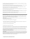
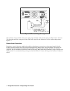
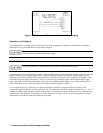
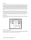
Figure 4-10. Recommended Protection Circuit for Battery Charging
Capacitive Load Limitation
The programmable overvoltage protection circuit can be used to downprogram capacitive loads although it is primarily
intended for use as a protection feature as described on page 48.
Repetitive (over 100 cycles) tripping of the overvoltage circuit with output capacitors greater than 2000
µ
F may result in eventual damage to the supply.
Parallel Operation
Connect in parallel only outputs that have equivalent voltage and current ratings.
Connecting outputs in parallel provides a greater current capability than can be obtained from a single output. Because each
output contains an active downprogrammer that is capable of sinking current from only ONE identical output, you can
parallel no more than two outputs. These outputs must have equivalent voltage and current capability. For example, on the
Agilent 6626A power supply, only outputs 1 and 2 or 3 and 4 may be connected together. On the Agilent 6625A supply,
none of the outputs may be connected together. If you are mixing different model supplies (i.e. an Agilent 6625A and an
Agilent 6626A) be sure to connect only equivalent voltage and current outputs in parallel.
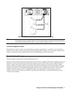
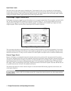
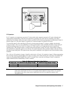
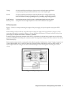
As an example, Figure 4-11 shows how to connect two outputs in parallel to a single load with local sensing. This
configuration applies to both CV and CC operating modes. Connecting the load leads of output 2 directly to the + V and - V
terminals of output 1 keeps the total length of the load leads to a minimum and reduces the number of wire connections that
must be made at the load itself. Connecting the + S and -S terminals of output 2 directly to the sense terminals of output 1
compensates for the IR drop in the interconnecting load leads.