


Command Summary
111
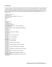
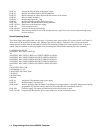
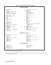
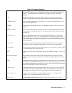
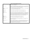
Table C-2 Command Summary
ASTS? < ch > Queries the accumulated status (ASTS) of the specified output < ch > . The response
(integer 0-255) represents the sum of the binary weights of the ASTS register bits (see
page 77). The ASTS register is automatically set to the present status after being
queried.
CLR Returns the entire power supply (all outputs) to the power on state, except that the
supply is not unaddressed and its store/recall registers are not changed (see page 76).
CMODE < on/off > Turns the calibration mode on or off. On/off is a 1 to turn the calibration mode on; a 0
turns it off (see Appendix A).
CMODE? Queries if the calibration mode is on or off. Response is either a 1 (on) or 0 (off), (see
page 82).
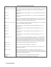
DCPON < on/off > Sets the state of the outputs at power-on. For on/off = 0, all outputs will be off when the
power supply is turned on. For on/off = 1 all outputs will be on when the power supply
is turned on.
DLY < ch >,< x > Sets the reprogramming delay time (x) for the specified output < ch > . This delay is
used to mask the CV, + CC, - CC, and UNR status bits from the fault register and the
OCP function for the specified delay period (0 to 32 seconds). The delay time is initiated
after a VSET, ISET, OUT, RCL, over voltage reset, or over current reset commands is
sent (see page 81).
DLY? < ch > Queries the present reprogramming delay of the specified output <ch> (see page 81).
The response can be a real number from 0.000 to 32 seconds (e.g. 0.450 seconds).
DSP < on/off> Turns the power supply’s front panel display either on or off (see page 81). On/off equals
1 to turn the display on or a 0 to turn it off.
DSP? Queries the present status of the display (see page 81). Response is either a 1 (on), or a 0
(off).
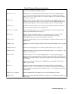
DSP “xxxxxxxxxxxx” Puts the quoted string on the power supply's front panel display (see page 81). Only
numerals, upper case letters, and spaces are allowed (12 characters max) in the quoted
string.
ERR? Queries the present programming or hardware error (see page 82). An error code number
is returned over the GP-IB to identify the error. In the local mode, pressing the error key
will cause the appropriate error message (not the error code) to be displayed on the front
panel. The error register is cleared after being read.
FAULT? < ch > Queries the fault register of the specified output < ch > (see page 77) . A bit is set in the
fault register when the corresponding bit is set in both the status and the mask registers.
The response is an integer 0 to 255. The fault register is cleared after being read.
IDAC < ch >, < x > Programs the current DAC to a specified number of counts < x > for the selected
channel < ch > . The number returned is in DAC counts.
IDAC? < ch > Queries the LSB setting of the current DAC for the selected channel < ch > . The
number returned is in DAC counts.