


Getting Started
35
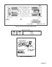
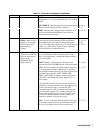
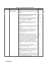
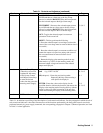
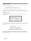
Table 3-1. Controls and Indicators (continued)
Number Controls/Indicators Description Page
7 (cont)
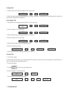
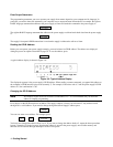
Ñ CURRENT - Increases the selected output current by
an LSB and then at a faster rate as the key is kept
pressed, or after the RANGE V/I key has been pressed,
sets the selected output to the high current range.
3-9, 6-3
Ò CURRENT - Decreases the selected output current
by an LSB and then at a faster rate as the key is kept
pressed, or after the RANGE V/I key has been pressed,
sets the selected output to the low current range.
3-9, 6-3
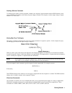
OCP - Toggles the selected output’s overcurrent
protection circuit on and off.
3-8
RESET - This key performs the following:
1. Reset the selected output’s overvoltage crowbar (the
cause of the overvoltage must be removed before reset is
successful) .
2. Reset the selected output’s overcurrent condition and
returns the output to its previous settings (the cause of
the overcurrent must be removed before reset is
successful).
3. Return the display to the metering mode from any
other mode (e.g. VSET). In the metering mode, the
measured output voltage and current of the selected
output are displayed .
3-8
8
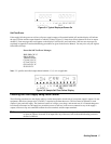
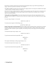
Numeric Entry Keys
(These keys are used in
conjunction with many
of the System Control
and Output Control keys
to enter the desired
values into the power the
metering mode. Supply.
0 to 9 - Set the value of the specified function and
and (e.g. VSET 1 6.550
.
Ï(backspace) - Erases the previous keystroke.
Depressing this key without setting a
value places the display in
ENTER - Enters the values on the display for the
specified function, initiates the function, and returns the
display to the metering mode. Pressing this key without
setting a value will result in retention of the previous
values and returning the display to the metering mode.
3-8,
6-1--6-5
6-1
3-8,
6-1--6-5
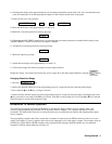
9
LINE switch
Turns ac power on and off.
3-6
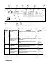
Table 3-1, in addition to providing a brief description of each control and indicator, lists the paragraphs in which the use of
each control and indicator is described. Because most of the functions performed by the front panel controls can also be
performed remotely by power supply commands, the corresponding paragraphs in Chapter 5 (Remote Operation) are listed
in Table 3-1 where applicable.