


Alignment Procedures
91
A
Alignment Procedures
Introduction
This appendix contains the software alignment procedures for the power supply. These supplies should be aligned twice a
year, or whenever certain repairs are made (see Service Manual).
The equipment that you need and the test setups to perform the alignment are also shown. A listing of the alignment
procedure appears at the end of Appendix A. Refer to Appendix C (Command Summary) for detailed explanations of the
commands used within the alignment program.
Because there are no internal or external hardware adjustments, your power supply can be aligned without removing the
covers or removing it from the cabinet if it is rack mounted. Alignment is performed by measuring actual output values and
sending them to the supply over the GP-IB.
Security against accidental alignment is available. A jumper inside the unit may be moved from NORMAL to CAL
LOCKOUT to disable all alignment commands. Access to this jumper requires opening the unit (see Service Manual).
If a number returned to the power supply is out of range while running the alignment program, the front panel ERR
annunciator will indicate an error. For example, an error will be created if the DMM is connected to measure a current
when a voltage measurement is anticipated by the program.
Note The memory used to store correction constants will accept and store data about 10,000 times, which is
more than sufficient for normal calibrations over the life of the instrument. However, do not put the unit
in a calibration loop that repeatedly turns the calibration mode on and off.
Test Equipment and Setup Required
The following test equipment is required for alignment:
1. A computer connected to the GP-IB connector on the back of the power supply.
2. An Agilent 3458A Digital Multimeter (DMM).
3. A precision 0.1 ohm
±
0.003%, 5 A shunt resistor (4 terminal). Recommended--Leeds & Northrop Part Number 4221-B
(in oil bath) or Guildline - Part Number 9330/.l/Agilent (in air).
In line 130, change the constant SHUNT_r to the actual measured value of the shunt being used.
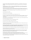
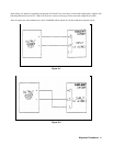
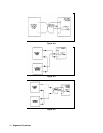
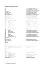
Figures A-1 through A-5 show setups required for aligning the power supply. You will be instructed by the program to
refer to a particular setup. Observe polarity when connecting the DMM.
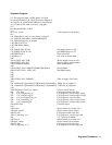
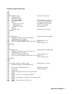
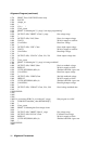
Calibration Program
The following alignment program can be used as is, provided you have an HP Series 200/300 computer with the BASIC
programming language and an Agilent 3458A DMM. Refer to Appendix C (Command Summary) for further information
on the commands used within the program.