


Remote Operation
75
Overcurrent Protection (OCP)
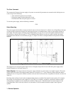
The OCP is a protection feature employed by the power supply to guard against excessive output currents. When the output
enters the + CC mode and the OCP is enabled, the OCP circuit down programs the output voltage and disables the output.
To enable the OCP, for output channel 1, send the command
OCP 1,1
To disable the OCP, send the command
OCP 1,0
You can find out the OCP setting by sending the following query and addressing the power supply to talk.
OCP? 1
The response from the power supply is either a "0’’ to indicate that OCP is off or a ’’1" to indicate that it is on. To reset the
output channel after an overcurrent trip, you can either disable the OCP and send the reset command, or you can reduce the
output current below the programmed current and then send the reset command. To reset output 1, send the command:
OCRST 1
Note The supply can report a fault condition when an output is in overvoltage or overcurrent. Although the
OVRST and OCRST commands re-enable the output, they do not clear the fault register. As a
housekeeping measure, it is advisable to always clear the fault register by querying its value after an OV
or OC reset.
Multiple Output Storage & Recall
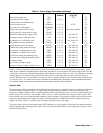
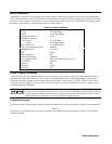
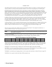
The power supply has 11 internal registers (0-10) each of which can store the voltage and current settings of all the outputs.
By storing voltage, voltage range, current, current range and OV settings for all outputs and recalling them later, you can
have significant savings in programming time. (See Supplemental Characteristics in Table 1-2). Upon shipment from the
factory, registers (1-10) contain values of 0 volts and 0 current (see Table 5-4).
Registers 0-3 are non-volatile. They are limited to one STORE each. If more than one STORE is attempted, error 30
(STORE LIMIT) will result. The line must be turned off/on to re-enable these store locations. Register 0 is a special case
that also contains Delay, Mask. When the power supply is turned on, it will access register 0 for power-up settings.
Registers 4-10 (volatile) will be reinitialized to 0 volts and 10 mA (max OV & V, I ranges = HIGH) when power is cycled
on/off.
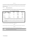
To store voltage and current settings, issue the store (STO) command and specify a register (0-10). For example, to store
the present setting of current and voltage of all outputs in register 2, send the following command:
STO 2
To set the power supply to the voltage, voltage range, current, current range, and overvoltage settings stored in a register,
issue the recall (RCL) command followed by the desired register. For example to recall settings stored in register 2, send
the following command:
RCL 2
When a register is recalled, the outputs will be set sequentially (output 1, output 2, etc.). If you attempt to recall a register
outside the 0 to 10 range, you will get a number range error (GP-IB code 5 in Table 5-8).