


Programming with a Series 200/300 Computer
108
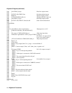
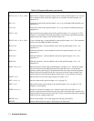
LINE 10: Assigns the I/O path name to the power supply.
LINE 20: Declares a common block for the I/O path name.
LINE 30: Defines interrupt on softkey depression and branch to error routine.
LINE 40: Idles on softkey definition.
LINE 80: Defines subprogram Err _ trap
LINE 90: Disables interrupt capability while processing.
LINE 100: Brings in the common block for the I/O pathname.
LINE 110,120: Enters error code from power supply.
LINE 130: Clears computer screen.
LINE 140,150: If an error occurred, print message.
LINE 170-420: Prints message based on error code. Prompt user to try again. If no error occurred, print message saying
no error occurred.
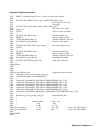
Stored Operating States
Your power supply has registers that can store up to 11 operating states (note registers 0-3 are non-volatile, see Chapter 3).
These states can be recalled in arbitrary order. Storing a state involves taking a "snapshot" of the voltage and current
settings that are in effect when the command is received. The following example uses stored operating states to set up an
output. Using this method of setting up outputs saves processing time and facilitates repeating the same commands.
10 ASSIGN @Ps TO 705
20 OUTPUT @Ps;’’OUT1,0;OUT2,0"
30!
40 OUTPUT @Ps;"VSET1,1;ISET1,0.01;VSET2,5;ISET2,0.01;STO1"
50 OUTPUT @Ps;"VSETl,2;ISETl,0.02;VSET2,4;ISET2,0.02;STO2"
60 OUTPUT @Ps;"VSETl,3;ISETl,0.03;VSET2,3;ISET2,0.03;STO3"
70 OUTPUT @Ps;"VSETl,4;ISETl,0.04;VSET2,2;ISET2,0.04;STO4"
80 OUTPUT @Ps;’’VSET1,5;ISET1,0.05;VSET2,1;ISET2,0.05;STO5"
90 !
100 OUTPUT @Ps;"CLR"
110 FOR State = 1 to 5
120 OUTPUT @Ps;"RCL";State
130 WAIT 2
140 NEXT State
150 END
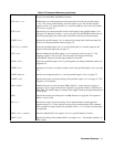
LINE 10: Assigns the I/O pathname to the power supply.
LINE 20: Disables Output 1 and Output 2.
LINE 40-80: Stores 5 operating states for Output 1 and Output 2 in storage registers 1 through 5. Outputs not explicitly
programmed will store the settings that are in effect when the store command is received.
LINE 100: Clears the supply. All outputs are enabled and set the initial power on state.
LINE 110-140: Loops through the sequence of five states with a two second wait between states.