


Output Connections and Operating Information
53
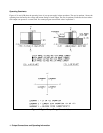
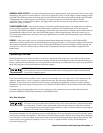
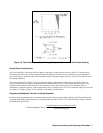
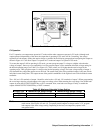
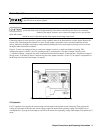
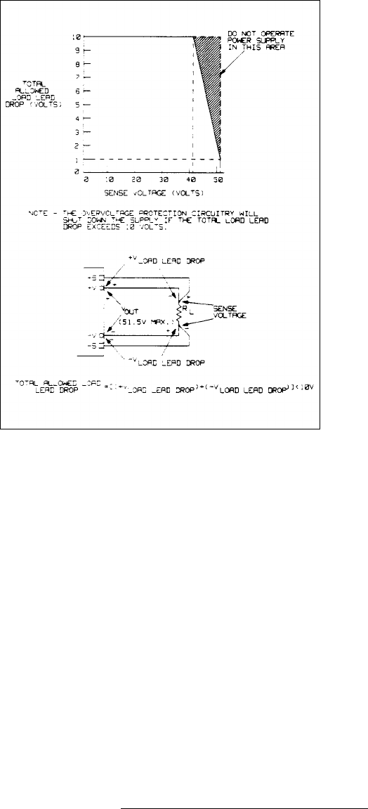
Figure 4-6. Total Allowable Load Lead Voltage Drop (total of both leads) with Remote Sensing
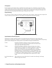
Output Noise Considerations
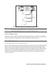
Any noise picked up on the sense leads will appear at the supply’s output and may adversely affect CV load regulation.
Twist the sense leads or use a ribbon cable to minimize the pickup of external noise. In extremely noisy environments it
may be necessary to shield the sense leads. Ground the shield at the power supply end only; do not use the shield as one of
the sensing conductors.
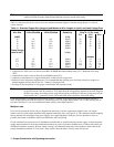
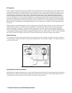
The noise specifications in Table 1-2 apply at the power supply output terminals when using local sensing. However,
voltage transients may be produced at the load by noise induced in the leads or by load current transients acting on the
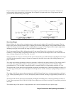
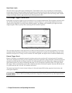
inductance and resistance of the load lead. If it is desirable to keep voltage transient levels to a minimum, place an
aluminum or a tantalum capacitor, with an approximate value of 10
µ
F per foot (30.5 cm) of load lead, right across the load
(see Figure 4-5). Refer to Figure 1-4 for capacitive load stability considerations.
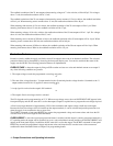
Programming Response Time with an Output Capacitor
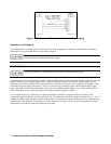
Because voltage programming into an external output capacitor may cause the supply to briefly enter CC operating mode,
voltage programming response time may be longer than that specified in Table 1-2. Use the following formula to estimate
the additional response time:
Additional Response Time
Added Output Capacitor)(Charge in Vout
Current Limit Setting
=
()