


Getting Started
32
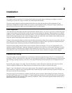
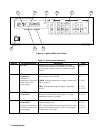
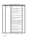
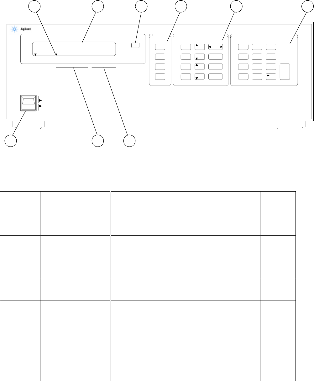
Figure 3-1. Agilent 6626A Front Panel
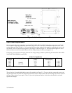
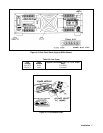
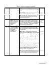
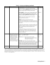
Table 3-1. Controls and Indicators
Number Controls/Indicators Description Page
1
LCL key
Returns power supply to local mode (unless local
lockout has been received via GP-IB). Also, turns the
power supply’s display on if it was turned off via the
GP-IB.
3-13, 5-2,
6-1
2
GP-IB Status
Annunciators
(These three
RMT - Indicates that the power supply is operating
under remote control (GP-IB)
3-13, 5-2,
6-1,
annunciators indicate the
GP-IB status of the
power supply).
ADDR - Indicates that the power supply is addressed to
talk or to listen.
3-10, 5-1
SRQ - Indicates that the power supply is requesting
service.
5-1, 5-2,
5-3, 5-17
3
OUTPUT
Annunciators
Indicate which output channel has been selected for
front panel control and/or display (Only one output
annunciator can be on at a time.)
3-7, 3-8,
6-1--6-4
4
Power Supply Status
Annunciators
CV - Indicates that the selected output channel is in the
constant voltage mode.
3-8, 4-1,
6-2, 6-3
(These five annunciators
indicate the status of the
power supply).
CC - Indicates that the selected output channel is in the
positive constant current mode ( + CC) or the negative
current limit ( - CC) mode.
3-8, 4-1,
6-2, 6-3
SYSTEM OUTPUT ENTRY
LINE
ON
OFF
LCL
ADDR
ERR
STO
RCL
RANGE
V/I
OVSET
RESET
OCP
VOLT
VOLT
CURR
CURR
OUTPUT
SELECT
VSET
ISET
OUTPUT
ON/OFF
ENTER
789
456
123
0
.
VOLTS AMPS
6626A SYSTEM DC POWER SUPPLY
1 2 3 4 CV CC UNR OCP ERR RMT ADDR SRQ
ENBLD-- OUTPUT --
45.153 14.235m
9 4 2
87613 5