


Output Connections and Operating Information
51
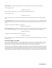
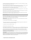
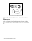
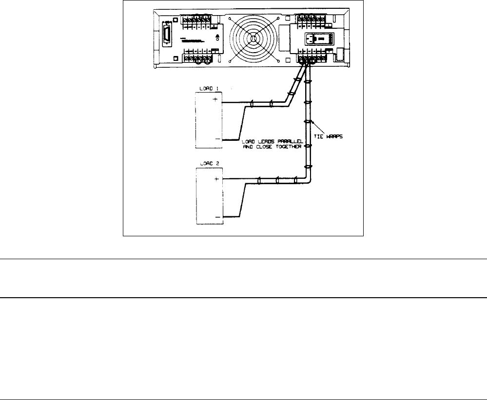
Figure 4-4. Optimum Hookup for Multiple Loads, Local Sensing
Note When a load is connected through relay or switch contacts, contact bounce may activate the overvoltage
circuit and shut down the supply. Therefore, it is recommended that the output be downprogrammed to 0
or turned-off (disabled) before the relay (or switch) contact is opened or closed.
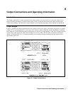
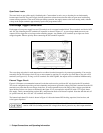
Positive and Negative Voltages
Either positive or negative voltages can be obtained from the supply by grounding (or "commoning") one of the output
terminals. Always use two wires to connect the load to the supply regardless of where or how the system is grounded. This
supply can be operated with any output terminal
±
240 Vdc (including output voltage) from ground.
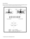
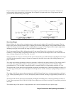
Remote Voltage Sensing
The power supplies will allow up to a total load lead drop of 10 V.
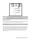
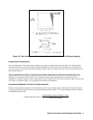
Because of the unavoidable voltage drop developed in the load leads, the as-shipped terminal block strapping pattern shown
in Figure 4-4 does not provide the best possible voltage regulation at the load. The remote sensing connections shown in
Figure 4-5 improve the voltage regulation at the load by monitoring the voltage there instead of at the supply’s outputs
terminals. This allows the power supply to automatically compensate for the voltage drop in the load lead. Remote sensing
is especially useful for CV operation with load impedances that vary or have significant lead resistance. It has no effect
during CC operation. Because sensing is independent of other power supply functions, remote sensing can be used
regardless of how the power supply is programmed. Note that with remote sensing, voltage readback monitors the load
voltage at the sense points.