


Alignment Procedures
92
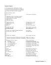
The program contains embedded comments (identified by a leading asterisk {! } ) which explain various sections and
procedures. To reduce keystroking, the program may be shortened to a minimum number of lines by eliminating these
comments.
The alignment program is available on a 5¼ floppy (Agilent P/N 06626-10001) or 3½ inch microfloppy (Agilent P/N
06626-10002). Both disks also contain a verification program, which tests the power supply's output programming and
readback accuracy to ensure that it is aligned correctly.
The program will automatically recognize what model power supply is being tested, the number of outputs the power
supply has, and which type output it is testing. Using this information, the program will calibrate each of the power supply.
After the program has finished calibrating the power supply, it will store the calibration constants and turn off the
calibration mode.
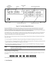
Type in the program and press RUN.
The program first does some "house keeping".
It will clear the screen, and assign a number of Common Variables (lines 100 - 130).
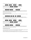
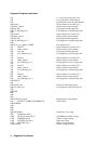
The program next assigns the address of the power supply to 705 (line 160) and the address of the DMM to 722 (line 170).
It will then assign the CRT as the output device (line 180) and the value of the current shunt. Enter the exact measured
value at line 190.
The power supply is sent a CLR command (line 210), which will set it to the turn on state. It will then identify what model
power supply is being tested (lines 220 and 230).
Next it will preset the DMM (line 250) and set the DMM sample (line 260).
It will now place the power supply in calibration mode (line 300).
The program is now ready to perform the calibrations on the power supply.
The program will first perform a subprogram (called at line 360 and performed in lines 3420 - 3630) which will set up the
output parameters of the output under test.
The program will then calibrate its voltage programming and readback circuitry (the subprogram is called at lines 370 and
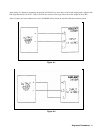
380, and performed in lines 1430 - 1920). During this subprogram, the controller will pause, and request that the user set up
the power supply and DMM referring to a figure in this Appendix. Press CONTINUE when ready.
Next the overvoltage circuitry will be calibrated (the subprogram is called in line 390, and performed in lines 1960 - 2070).
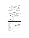
The current alignment tests on the 2 Amp, 50 W outputs are made using a shunt, be sure that the DMM is connected to the
HI and LO voltage input terminals when the shunt is used.
The current circuitry will be calibrated next (the subprograrn is called in lines 400 and 410, and performed in lines 2110 -
2700). During this subprogram, the controller will pause and request that the user set up the power supply and DMM
referring to a figure in this Appendix. Press CONTINUE when ready.
Finally the program will calibrate its current sink readback circuitry (performed in lines 2740 - 3380).
To perform the current sink readback alignment on the Agilent 6626A, outputs of equivalent current capability are used as
pairs. For example outputs 1 and 2 are used to test each other, the outputs 3 and 4 are used to test each other.
In order to perform the current sink readback alignment on the Agilent 6625A, the program automatically limits the current
of output 2 (the 50 W output) to 0.5 Amps (line 2780).