


Output Connections and Operating Information
61
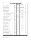
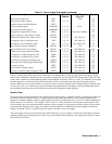
Voltage All series specifications referring to voltage are twice the single output specification
except for programming resolution which is the same as for a single output.
Current All series specifications referring to current are the same as for a single output except
for CC load effect, CC load cross regulation, CC source effect, and CC short term drift
which are twice the current programming accuracy (including the percentage portion).
Load Transient
Recovery Time
Load transient recovery time is the same to within approximately twice the voltage
setting band since the output impedances of the series combination add together.
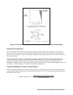
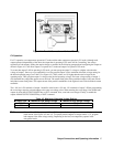
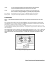
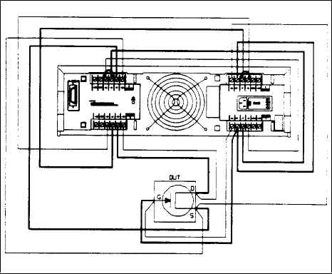
Bi-Polar Operation
Figure 4-15 shows an example connecting the outputs of the power supply for bi-polar operation to test power FET’s
(PFET).
Great flexibility is achieved with this setup. The outputs of the power supply can be programmed as voltage or current
sources providing positive or negative voltages or currents. By taking measurements via internal readback circuitry in the
power supply, the outputs can be used as voltmeters or ammeters.
In order to properly measure the parameters of the PFET, it is desirable to be able to directly regulate any two of the bias
parameters of the PFET, while being able to measure a third. The setup shown in Figure 4-15 allows control of Vds and Ids
while measuring Vgs.
In this example, outputs 3 and 4 are connected to allow bipolar operation. Notice that the - S and - V leads, of outputs 3 and
4, are strapped together. The + S lead of V3 senses the voltage at the drain of the Device Under Test (DUT) and the + S
lead of output 4 senses the voltage at the source of the DUT. Outputs 1 and 2 are strapped to sense the gate to source
voltage.
Figure 4-15. Bipolar Operation