


Installation26
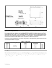
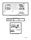
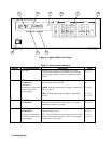
Figure 2-1. Outline Diagram
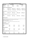
Input Power Requirements
You can operate this power supply from a nominal 100 V, 120 V, 220 V or 240 V single phase power source at 47 to 66
Hz. The input voltage range, maximum input current, high line inrush current (PK), and the fuse required for each of the
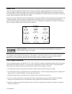
nominal inputs are listed in Table 2-1. You can check the line voltage setting of your supply by examining the door on the
line module. This is located on the rear panel of your supply as shown in Figure 2-2. The red mark that appears in one of
the four windows on the line module indicates the line voltage setting for which your supply is set.
If necessary, you can convert the supply from one line voltage setting to another by following the instructions under LINE
VOLTAGE CONVERSION (see page 29).
Table 2-1. Input Power
Nominal
Voltage
Line Voltage Range Maximum Input Current
(rms.)
High Line Inrush
Current (PK)
Fuse
100 V 6.3 A 85 A 8 AM
120 V Nominal 5.7 A 85 A 8 AM
220 V -13%, +6% 3.0 A 50 A 4 AM
240 V 3.0 A 50 A 4 AM
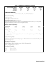
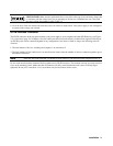
Line Fuse
The ac line fuse is located behind the door on the line module (see Figure 2-3). To access the fuse, remove the power cord
and push against the tab on the line module in the direction of the ac input socket. The current rating of the fuse is based on
the line voltage setting of your supply. Table 2-2 gives the Agilent part numbers for the fuses that should be used with
specific line voltages.