


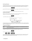

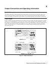

Output Connections and Operating Information
48
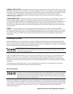
The readback resolution of the 25 watt outputs when metering voltages of 7 volts or below, will be 483
µ
V. For voltages
above 7 volts, the readback resolution will be 3.3 mV.
The readback resolution of the 25 watt outputs when metering source currents of 15 mA or below, the readback resolution
will be 1
µ
A. When metering source currents above 15 mA, the readback resolution will be 48
µ
A.
When metering sink currents of 15 mA or below, the readback resolution of the 25 watt outputs will be 1
µ
A. When
metering sink currents above 15 mA, the readback resolution will be 37
µ
A.
When metering voltages of 16 volts, or below, the readback resolution of the 50 watt outputs will be 1.1
µ
V. For voltages
above 16 volts. the readback resolution will be 3.3 mV.
When metering source currents of 200 mA or below, the readback resolution of the 50 watt outputs will be 14
µ
A. When
metering source currents above 200 mA, the readback resolution will be 160
µ
A.
When metering sink currents of 200 mA or below, the readback resolution of the 50 watt outputs will be 14
µ
A. When
metering sink currents above 200 mA, the readback resolution will be 151
µ
A.
Protection Features
Protective circuitry within the supply can limit or turn off an output in the event of an abnormal condition. The activated
protection feature can be determined by observing the front panel display area. You can also read back the status of the
supply over the GP-IB. The following protection features are implemented:
OVERVOLTAGE -- shorts the output by firing an SCR crowbar and sets zero volts and minimal current on an output if
any of the following conditions are present:
1. The output voltage exceeds the programmed overvoltage trip point.
or
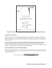
2. The sum of the voltage from the + V output terminal to the +S terminal plus the voltage from the -S terminal to the -V
output terminal exceeds 10.0 V (applies to remote sensing only).
or
3. A trip signal is received on the output’s OV terminals.
or
4. The output’s fixed overvoltage circuit is activated.
The OV trip point can be programmed up to 55 V. When an overvoltage occurs, the word OVERVOLTAGE appears in the
front panel display and the OV status bit is set for that output. Chapter 5 explains how to program the overvoltage trip level.
A fixed overvoltage threshold of approximately 120% of the maximum rated output voltage is built into each output.
Because the fixed overvoltage circuit is biased from the output terminals, it can be activated and provide protection even
when the supply is not connected to the ac power line.
The OVRST command or front panel RESET key restores the programmed voltage and current values and clears the OV
once the cause of the overvoltage has been eliminated.
OVERCURRENT -- when the overcurrent protection feature is enabled, and the output is sourcing current and enters the +
CC operating mode, the output will be disabled (set to zero volts and minimal current) and the word OVERCURRENT will
appear on the front panel display. In addition, the OC status bit is set for that output. The OCRST command or front panel
RESET key restores the programmed voltage and current values and clears the OC once the cause of the overcurrent
condition has been eliminated. Refer to Chapter 5 for programming details.