


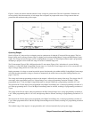
Output Connections and Operating Information
50
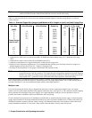
Note To prevent tripping of the overvoltage circuit, pick a wire size sufficient to handle the FULL output
current of the unit no matter what the intended load current or current limit setting.
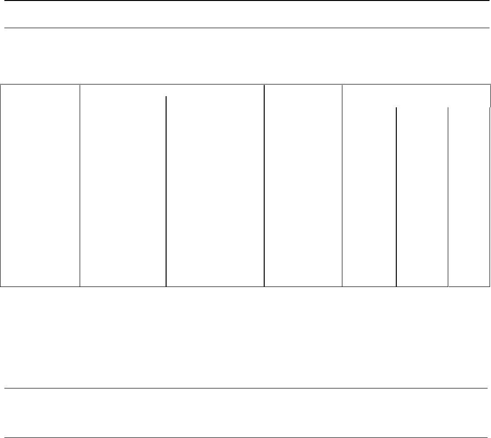
Table 4-1 lists the resistivity for various wire sizes and the maximum lengths to limit the voltage drop to 1.0 volts for
various currents.
Table 4-1. Stranded Copper Wire Ampacity and Maximum Wire Lengths to Limit Load Lead Voltage Drop
Ampacity Per Wire (Amps)
Max Length to Limit Voltage
Wire Size 2 Wire Bundled 4 Wire Bundled Resistivity Drop to 1 V Per Lead
5 A 10 A 20 A
(AWG)
(Ω/ft)
(feet)
20 7.8 6.9 0.0102 20 10 5
18 14.5 12.8 0.0064 30 15 7.5
16 18.2 16.1 0.0040 50 25 12.5
14 29.3 25.9 0.0025 -- 40 20
12 37.6 33.2 0.0016 -- -- 30
(Cross Section
Area in mm
2
)
(Ω/m)
(meters)
0.5 7.8 6.9 0.0401 5 2.4 1.2
0.75 9.4 8.3 0.0267 7.4 3.8 1.8
1 12.7 11.2 0.0200 10 5 2.6
1.5 15.0 13.3 0.0137 14.6 7.2 3.6
2.5 23.5 20.8 0.0082 -- 12.2 6
Notes:
1. Ampacities for AWG wires are derived from MIL-W-5088B. Maximum ambient temp: 55°C. Maximum wire temp:
105°C.
2. Ampacities for metric wires are derived from IE Publication 335-1.
3. Ampacity of aluminum wire is approximately 84% of that listed for copper wire.
4. Because of wire inductance considerations, it is recommended that you keep your load leads twisted, tie wrapped, or
bundled together and less than 50 feet (14.7 meters) in length per lead.
5. See Page 49 for information on wire gauge considerations with capacitive loads.
Note The OVP circuit senses at the main output terminals and not on the sense leads. Thus, the voltage sensed
by the OVP circuit could be as much as 10 V higher than the voltage being regulated at the load. Program
the OVP trip voltage accordingly when using remote sensing. In addition, if the total voltage drop in both
leads exceeds 10 V, a protective circuit will fire the OVP circuit regardless of the OVP setting.
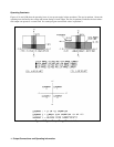
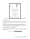
Load lead resistance is an important factor relating to the CV stability of the supply with remote sensing of capacitive
loads. If high capacitance loads are expected, you should not use wire gauges heavier than 12 to 14 AWG for long runs of
load lead. See Figure 1-4 for more information about stability with output capacitors.
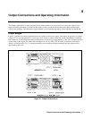
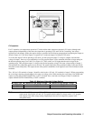
Multiple Loads
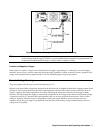
If you will be sensing the load locally (as shipped from the factory) and are connecting multiple loads to one output,
connect each load to the output terminals using separate connecting wires (see Figure 4-4). This minimizes mutual coupling
effects and takes full advantage of the power supply's low output impedance. Each pair of wires should be as short as
possible and twisted or bundled to reduce lead inductance and noise pickup.
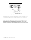
If load considerations require the use of distribution terminals that are located remotely from the supply, connect the power
supply output terminals to the remote distribution terminals by a pair of twisted or bundled wires. Connect each load to the
distribution terminals separately. Remote voltage sensing is recommended under these circumstances. Sense either at the
remote distribution terminals or, if one load is more sensitive than the others, directly at the critical load.