


Getting Started
31
3
Getting Started
Introduction
This chapter is intended for the first time user of the supply. It provides four main discussions:
•
Front Panel Controls and Indicators
•
Turning on Your Supply
•
Checking Out Your Supply Using Local Control
•
Introduction to Remote Operation
First, the supply’s front panel controls and indicators are briefly described. Some of the controls and indicators will be used
in the Turn On And Checkout procedures that follow. Chapter 6 describes how to use all of the front panel controls.
Successful completion of the Turn On And Checkout procedures ensures with a high level of confidence that your supply is
operating properly. Complete performance testing and troubleshooting procedures are given in the Service Manual (Agilent
Part No. 06626-90003).
The checkout procedures are performed locally from the front panel. In addition to checking the operation of your supply,
these simple step-by-step checkout procedures will help the first time user become familiar with operating the supply from
the front panel.
When you have completed the checkout procedures, you are then introduced to the fundamentals of operating the supply
remotely from a computer. You will learn how to send a command to the supply from the computer and how to get data
back to the computer from the power supply. A few of the most often used power supply commands will be described to
help you get started and become familiar with the basics of programming your supply.
After completing this chapter, you can proceed to Chapter 4 to find out how to make load connections to your supply’s
outputs and then to Chapter 5 (Remote Control) and/or Chapter 6 (Local Control) to learn all the details about operating
your supply.
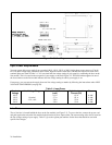
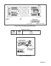
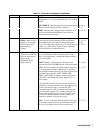
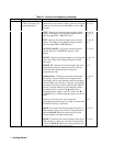
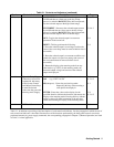
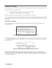
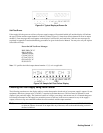
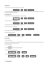
Front Panel Controls and Indicators
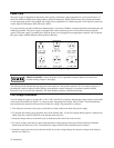
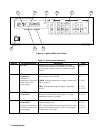
The power supply’s controls and indicators are shown in Figure 3-1 and are described in Table 3-1. Note that the front panel
controls are identical for all models except for the number of OUTPUT annunciators (number 3 in Figure 3-1).