


General Information
11
1
General Information
Introduction
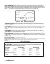
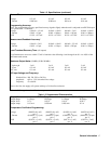
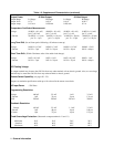
This chapter contains a general description of your power supply as well as its performance specifications. Information
about options, accessories, and GP-IB cables is also provided. This manual describes the Agilent 6625A, 6626A, 6628A,
and Agilent 6629A power supplies. Unless stated otherwise, the information in this manual applies to all of these models.
Information that is specific to one model only is identified as such in this manual.
Safety Considerations
This product is a Safety Class 1 instrument, which means that it is provided with a protective earth terminal. This terminal
must be connected to a power source that has a 3-wire ground receptacle. Review the instrument and this manual for safety
markings and instructions before operation. Refer to the Safety Summary page at the beginning of this manual for a
summary of general safety information. Safety information for specific procedures is located at appropriate places in this
manual.
Instrument and Manual Identification
Agilent Technologies power supplies are identified by a two-part serial number, i.e. 2601A-00101. The first part of the
serial number (the prefix) is a number/letter combination that denotes either the date of manufacture or the date of a
significant design change. It also indicates the country of origin. (Starting at 1960, 26 = 1986; 01 = the first week of the
year; A = U.S.A.) The second part of the serial number is a different sequential number assigned to each instrument starting
with 00101.
If the serial number prefix on your power supply differs from that shown on the title page of this manual, a yellow Manual
Changes sheet that is supplied with this manual explains the difference between your instrument and the instrument
described by this manual. The change sheet can also contain information for correcting errors in the manual.
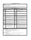
Options
Options 100,120, 220, and 240 simply determine which line voltage is selected at the factory. For information about
changing the line voltage setting, see line voltage conversion paragraph on page 29.
Option 750 consists of a fault indicator (FLT) and remote inhibit (INH) circuit and relay control, which provide additional
shutdown protection should either the GP-IB and/or controller fail. This Option is described in a separate document
entitled, ’’Appendix E Option 750 Operating Instructions for the Multiple Output Linear System DC Power Supply, Agilent
Models 6621A, 6622A, 6623A, 6624A, and 6627A’’ (Agilent P/N 5957-6372).
#100 Input power, 100 Vac, 47-66 Hz
#120 Input power, 120 Vac, 47-66 Hz
#220 Input power, 220 Vac, 47-66 Hz
#240 Input power, 240 Vac, 47-66 Hz
#750 Fault (FLT) Remote Inhibit (INH) and Relay Control
#908 One rack mount kit (5062-3977)
#909 One rack mount kit with handles (5062-3983)
#910 One service manual with extra operating manual