


Output Connections and Operating Information
60
CC Operation
For CC operation, the current setting of each output must be programmed to the desired operating current. The sum of the
voltage settings determines the voltage limit point. As an example, one way to program the voltage of the output is to set
the voltage of each output to one half of the total voltage limit point. Then, at load voltages less than one half of the total
voltage limit point, one output will operate in CC mode while the other output will be conducting through its internal
reverse voltage protection diode. At load voltages greater than one half the total voltage limit point, the output that was in
CC mode will change to CV mode while the output that was conducting through its diode will regulate the current in CC
mode and provide the balance of the voltage required by the load. Note that the total load voltage can be found by adding
the results of reading back the individual series outputs only when neither reverse voltage protection diode is conducting.
When this diode is conducting, the corresponding output has reverse voltage across it so that its voltage readback may not
be accurate.
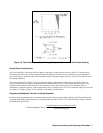
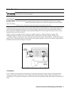
When an output is conducting through its reverse voltage protection diode, the output will have a reverse voltage across its
output terminals with the - V terminal more positive than the + V terminal. This voltage will be maximum at the rated
current of the output. (See Figure 4-2 for reverse diode characteristic). Note that when an output conducts through this
diode, it will indicate CC mode even though it is not regulating the current or voltage. Also, note that the voltage readback
is not specified to indicate negative voltages although it will operate down to a limit of about - 0.176 V on the 25 W outputs
and -0.392 V on the 50 W outputs. These values will still be indicated even if the actual voltage is more negative.
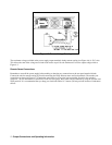
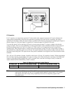
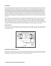
Remote Sensing
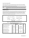
If it is necessary to remote voltage sense at the load, connect the sense leads of output 1 and output 2 as shown in Figure 4-
14. Note that the + sense lead of output 2 must remain connected to the -sense terminal of output 1. The outputs may be set
as previously described.
Figure 4-14 Series Connections with Remote Sensing
Specifications for Series Operation
Specifications for outputs operating in series can be obtained from the specifications for single outputs. Most specifications
are expressed as a constant or a percentage (or ppm) plus a constant. For series operation, the percentage portion remains
unchanged while constant portions or any constants are changed as indicated below.