


Local Operation
85
6
Local Operation
Introduction
Chapter 3 introduced you to the supply’s front panel controls and indicators to help you turn on the supply and perform the
checkout procedures that were given in that chapter. The following paragraphs describe how to use all of the front panel
controls and indicators. Most of the remote operations described in Chapter 5 can also be performed locally from the
supply’s front panel.
Local Mode
In order to use the front panel keys to control the supply, the local mode must be in effect. The local mode is in effect
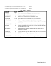
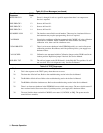
immediately after power is applied. Table 5-3 lists the initial settings for all of the power supply’s functions when power is
initially applied. When the local mode is in effect (RMT annunciator off), the Output Function, System Function, and
Numeric Entry keys on the front panel (see Figure 6-1) can be used to operate the power supply.
In the remote mode (front panel RMT annunciator on), the front panel keys will have no effect on any of the supply’s
outputs and only the computer can control the supply. You can, however, still use the front panel display to view the output
voltage and current readings or the present settings for the selected output channel while the supply is in the remote mode.
You can return the supply to the local mode from the remote mode by pressing the LCL key provided that the local lockout
command has not been received from the GP-IB controller. Pressing the LCL key will also turn the supply’s display back
on if it was turned off with a DSP command during remote operation (see page 81). A change between the local and remote
modes will not result in a change in the power supply’s outputs.
Local Control Of Output Functions
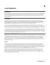
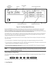
The Output Function keys (see Figure 6-1) allow you to control the selected output. Figure 6-1 shows the annunciator arrow
over OUTPUT 2 indicating that output channel 2 is selected. Pressing the OUTPUT SELECT key selects the output
channels in forward (
>
) or reverse (
<
) sequence. Note that Figure 6-1 illustrates the front panel for the Agilent 6626A
supply which has four output annunciators. The front panel for Agilent Model 6625 is identical to Figure 6-1 except it has
two output annunciators.
General
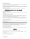
The power supply will accept programming values directly in volts and amps. The programmable voltage, current, and
overvoltage ranges for the outputs of each model are given in Table 5-4. The power supply will round off the values
received to the nearest multiple of the resolution for that particular output. If you send a value out of the valid range, it will
not be executed and the ERR annunciator will come on. You can get a readout of the error on the display by pressing the
ERR key. For an out-of-range error, the error message ’’NUMBER RANGE" will be displayed.
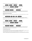
When you press the VSET, ISET, or OVSET key, the output selected and the present setting for that function will be
displayed. You can change the setting using the numeric entry keys. Pressing the number keys will cause the present
numeric setting to become blank and be replaced with the new numbers on the display. You can use the Ï key to erase
previous keystrokes if you make a mistake.