


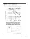


Installation
29
FIRE HAZARD. Make sure the replacement fuse is one of the same type (size) and rating (amps) that
is consistent with the voltage level you are operating at. Do not use a substitute fuse; use a fuse with
the same Agilent Part number listed in Table 2-2.
6. Close the door of the line module and insert the power cord in the ac input socket. Your power supply is now configured
to operate at the voltage you selected.
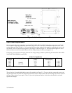
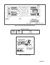
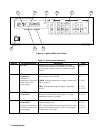
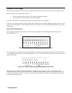
GP-IB Interface Connector
The GP-IB connector on the rear panel connects your power supply to your computer and other GP-IB devices (see Figure
2-2). Accessories (page 12) in Chapter 1 lists the cables and cable accessories that are available from Agilent Technologies.
An GP-IB system can be connected together in any configuration (star, linear, or both) as long as the following rules are
observed
1. The total number of devices, including the computer, is no more than 15.
2. The total length of all the cables used is no more than two meters times the number of devices connected together, up to a
maximum of 20 meters.
Note IEEE Std. 488-1978 states that you should exercise caution if your individual cable lengths exceed 4 m.
Do not stack more than three connector blocks together on any GP-IB connector. The resultant leverage can exert excessive
force on the mounting panels. Make sure that all connectors are fully seated and that the lock screws are firmly finger
tightened. Do not use a screwdriver. Use a screwdriver only for the removal of the screws.