


Remote Operation
67
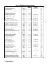
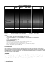
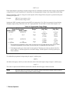
Table 5-1. Power Supply Commands (continued)
Command Header Output
Channel
Data Range
(Fig. 5-2)
Syntax
Store present output state STO 0-10 C2
Query preset status of output STS? 1, 2, 3, 4 Q2
Perform self test on GP-IB interface TEST? . C1
Set bits in mask register UNMASK 1, 2, 3, 4 0-255 C4
Query bits set in mask register UNMASK? 1, 2, 3, 4 Q2
Program the voltage DAC in counts VDAC 1, 2, 3, 4 See Service Manual C4
Querys setting of voltage DAC in counts VDAC? 1, 2, 3, 4 Q2
Send data to calibrate the voltage circuits VDATA 1, 2, 3, 4 See Table 5-4 C5
Set output to high V calibration value VHI 1, 2, 3, 4 See Table 5-4 C3
Set output to low V calibration value VLO 1, 2, 3, 4 See Table 5-4 V C3
Query inputs of analog multiplexer VMUX? 1, 2, 3, 4 1-18 C4
Query measured value of an output VOUT? 1, 2, 3, 4 See Table 5-4 Q2
Calibrate the voltage readback circuitry VRDAT 1, 2, 3, 4 See Table 5-4 C5
Set output to V readback high cal value VRHI 1 2, 3, 4 See Table 5-4 C3
Set output to V readback low cal value VRLO 1, 2, 3, 4 See Table 5-4 C3
Set full scale voltage programming range VRSET 1, 2, 3, 4 See Table 5-4 C4
Query full scale voltage programming range VRSET? 1, 2, 3, 4 See Table 5-4 Q2
Set output voltage VSET 1, 2, 3, 4 See Table 5-4 Q2
Query setting of output voltage VSET? 1, 2, 3, 4 See Table 5-4 Q2
Increase or decrease output voltage by value VSTEP 1, 2, 3, 4 See Table 5-4 C4
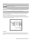
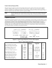
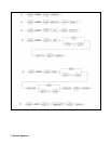
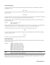
Figure 5-2 shows the possible syntax forms for the device commands that are used to program the power supply. Syntax
forms for the calibration commands that are discussed in Appendix A are also included. The oblong shape at the left of the
syntax forms contains the command header which must be entered as shown in Tables 5-1 and 5-2. Commands are accepted
in either uppercase or lowercase letters (ASCII characters). Circles contain characters that must be entered exactly as
shown. Characters such as a space <SP> or a comma are used to separate elements in the command string. Characters such
as a line feed < LF > or a semicolon are used to terminate the command string. Rectangles contain parameters that follow
the command header lines and arrows indicate the correct paths through the syntax diagrams.
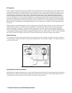
Numeric Data
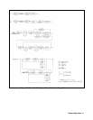
The power supply will accept numeric data in implicit point, explicit point, or scientific notation. A general syntax diagram
for numeric data is included in Figure 5-2. Implicit point notation means that numbers do not contain a decimal point;
integers for example. Numbers written in explicit notation contain a decimal point, such as 12.35. In scientific notation, the
letter E stands for "10 raised to". For example, 1.2E3 is read as 1.2 times 10 raised to the 3rd power, which equals 1,200.
Plus and minus signs are considered numeric characters and are optional. If you program a number with an accuracy that is
greater than the resolution of the supply, the number will automatically be rounded to the nearest multiple of the power
supply’s resolution. Table 5-1 gives the ranges for numeric data that is sent to the supply.
The power supply will also return numeric data (ASCII characters) to your computer. The format of the numbers returned
depends upon the type of data requested. Table 5-2 gives the format for data returned to the computer in response to any of
the queries that are listed.