


Installation
25
2
Installation
Introduction
This chapter contains instructions for checking and mounting your power supply, connecting your supply to ac power,
converting it from one line voltage to another, and connecting the GP-IB cable.
The power supply generates operating magnetic fields which may affect the operation of other instruments. If your
instrument is susceptible to magnetic fields, do not locate it in the immediate vicinity of the power supply. Typically, at
three inches from the power supply, the electromagnetic field is less than 5 gauss.
Initial Inspection
Your instrument was thoroughly inspected and tested before it left the factory. As soon as you receive it, remove the power
supply from its packing case and check to make sure it has not been damaged in shipment. Check that there are no broken
connectors or keys, and that the cabinet and panel surfaces are free from dents and scratches. Check the rear panel terminal
blocks and front panel display for any cracks. If damage is found, you should file a claim with the carrier immediately and
notify the Agilent Technologies Sales and Service office nearest you.
Chapter 3 of this manual includes an electrical turn-on check-out procedure which, when carried out successfully, will give
you a high level of confidence that the power supply is operating in accordance with its specifications. Detailed electrical
checks complete with verification procedures are included in the Service Manual.
Keep the original packing materials for the carrier’s inspection if there was damage, or in case any equipment has to be
returned to Agilent Technologies. Warranty information is printed on the inside cover of this manual. Remember to send a
detailed description of the failure and symptoms when returning the power supply for service. Your Agilent Technologies
Sales and Service office will furnish the address of the nearest service office to which the instrument can be shipped.
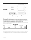
Location and Cooling
Your power supply can operate without loss of performance within the temperature range of 0 to 55 ° C (measured at the
fan intake). The fan, located at the rear of the unit, cools the supply by drawing air in through the openings on the rear panel
and exhausting it through openings on the sides. Using Agilent Technologies rack mount kits will not impede the flow of
air.
Because the power supply is fan cooled, it must be installed in a location that allows sufficient space at the rear and the
sides for adequate circulation of air. Either side may be restricted to have as little as 1 inch (25 mm) space.
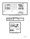
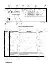
Figure 2-1 gives the dimensions of the power supply cabinet. These dimensions apply to both models. The cabinet has
plastic feet that are shaped to ensure self-alignment when stacked with other Agilent Technologies System II cabinets. The
feet may be removed for rack mounting.
The power supply can be mounted in a standard 19 inch rack panel or enclosure. Rack mounting accessories for this unit
are listed under options (page 11) of Chapter 1. Complete installation instructions are included with each rack mounting kit.
Instrument support rails are required for non-stationary installations. These are normally supplied with the cabinet and are
not included with the rack mounting kits.