


Getting Started
33
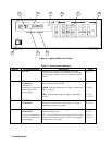
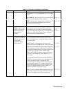
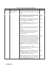
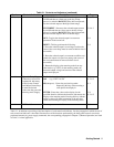
Table 3-1. Controls and Indicators (continued)
Number Controls/Indicators Description Page
4 (cont) UNR- Indicates that the selected output channel is
unregulated; i.e., it is not regulated by CV or CC control
loops.
4-4
OCP ENBLD - Indicates that the overcurrent protection
function for the selected channel is enabled.
3-8, 6-4,
5-13
ERR - Indicates that a programming or hardware error
has occurred and that the ERR bit in the serial poll
register has not been cleared
4-4, 5-16
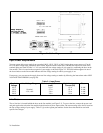
5 Alphanumeric LCD
Display (When power is
turned on, all segments
will be displayed for
approximately 2
seconds).
Normally displays the measured output voltage and
current for the selected channel. When programmed
from the front panel, the function being programmed
(e.g. VSET), the output channel (e.g. 2), and the present
value (e.g. 2.250) will be displayed. Error conditions
will be spelled out in alpha characters
3-7--3-10,
4-4, 5-19,
5-20,
6-1--6-4
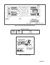
6 System Control Keys
(These four control keys
affect the entire power
supply and are
independent of the
ADDR - Displays the power supply’s GP-IB address.
You can change the address using the numeric entry
keys. You cannot query or change the address remotely
(over the GP-IB).
3-10, 5-2,
6-4
output selected.) ERR - Displays a programming or hardware error
message and clears the ERR bit in the serial poll register
5-1, 5-20
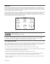
STO - Used in conjunction with the numeric entry keys
to store the present output conditions for all outputs in
the specified internal register (0-10). Each register stores
the following parameters: VSET, VRSET, ISET,
IRSET, and OVSET. In addition, register 0 also stores
OCP, DLY, and MASK parameters. Register 0-3 are
non-volatile.
5-1, 5-13
The parameters stored in register 0 are the "power-up"
parameters. These parameters are set upon applying AC
power to the power supply. Note that the STO
command cannot be used over the bus more than once
per non-volatile register (0-3) without cycling the AC
power (OFF and ON). However, these registers can be
used for an unlimited number of times via the front
panel keys without cycling the AC power .
RCL - Used in conjunction with the numeric entry keys
to recall the settings from the specified internal register
(0 to 10). All outputs are set to the recalled values.
5-1, 5-13