


General Information
13
The power supplies allow up to a 10 volt sense lead drop. This feature makes them ideal for test system applications where
remote sensing is used.
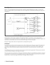
The output voltage and current for any output can be monitored with the front panel display. Output specific error messages
are also displayed. Front panel annunciators show the operating status of the instrument. The front panel keypad lets you set
and readback the voltage limit, current limit, and overvoltage trip level of any output. With the keypad, you can also enable
or disable outputs, enable overcurrent protection, reset overvoltage and overcurrent protection, and return to local operating
mode.
Your multiple output power supply can be both a listener and a talker on the GP-IB. (GP-IB is Agilent Technologies’
implementation of IEEE-488). The built-in interface is tailored to the supply, resulting in simpler programming. Voltage
and current settings can be sent directly to the specified output in volts and amps.
Service can be requested from your power supply for up to 10 reasons. The supply responds to a serial poll by identifying
the output on which the fault occurred. Self-contained measurement and readback capability eliminate the need for
externally scanning the outputs using a separate DVM. Upon command, the supply will measure its output voltage or
current and return the value on the GP-IB. The following functions are implemented via the GP-IB:
Voltage and current programming.
Programmable resolution range.
Voltage and current measurement and readback.
Present and accumulated status readback.
Programmable service request mask.
Programmable overvoltage and overcurrent protection.
Voltage and current range programming.
Storage and recall of programmed voltage and current values for all outputs.
Queries of programmed functions or settings.
Output enable or disable.
Programming syntax error detection.
Programmable delay time for service request and OCP mask.
Voltage, current, and overvoltage calibration.
GP-IB interface selftest.
Message display capability on the front panel.
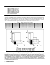
Output connections are made to rear panel screw terminals. Either the positive or negative output terminal can be grounded,
or the output can be floated up to
±
240 Vdc (including output voltage) from chassis ground. Output voltage can be locally
or remotely sensed, and identical outputs can be operated in series or parallel combinations for increased output voltage or
current capability. As shipped from the factory, the power supply is jumpered for local sensing.
Your power supply can be calibrated without having to remove the cover or even having to remove it from your system
cabinet. This feature allows you to calibrate the supply at its normal operating temperature. The recommended calibration
interval is one year. Refer to Appendix A of this manual for complete calibration details. A calibration security jumper is
available inside the unit. Access is described in the service manual.