


Getting Started
36
Turning On Your Supply
The following paragraphs describe the power-on sequence which includes a self test of most of the power supply’s circuits.
Before you turn on your supply, make sure that:
•
The line module on the rear panel is set to match your input line voltage.
•
The proper fuse is installed and the line cord is plugged in.
If you have any questions concerning installation or power requirements, review Chapter 2.
To turn on your supply, press the front panel LINE switch. When the power is initially applied, the supply performs a series
of self tests which last about 3 seconds. Included in these tests are checks of circuits on the GP-IB board and on each of the
output boards.
Normal Self Test Indications
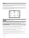
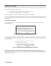
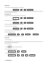
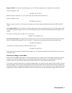
If the supply passes the self test, the display will first show all segments of the LCD display with annunciators on as
illustrated in Figure 3-2.
Figure 3-2. Test Pattern of all Display Segments at Power-on
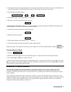
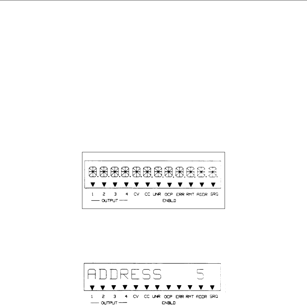
After all segments are displayed, the supply’s GP-IB address will appear for approximately 2 seconds as shown in Figure 3-
3. As shipped from the factory, the power supply’s address is set to 5. You must know this address before you can remotely
program your supply.
Figure 3-3. Typical Address Display During Power-On Self Test
When self test is successfully completed, the power-up parameters stored in register 0 will be set (see page 89 for a
complete description of the store and recall functions). As shipped from the factory, this non-volatile register contains zero
volts and zero current (see Table 5-4 on page 72) for all outputs. Note that the CV annunciator will indicate that the output
is in the constant voltage mode.