


Remote Operation
78
UNMASK 2,XXX
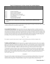
where XXX specifies the numeric code (0 to 255) for the unmasked conditions (see Table 5-5). If during operation, the
output experiences any of the previously unmasked conditions, it will set the corresponding bit(s) in its fault register.
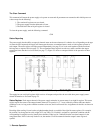
Remember that the bits in the fault register can be set when there is a change in either the status register or the mask
register. Each output has its status, mask, and fault registers arranged as shown in Figure 5-3 and Table 5-5. The mask
register, which is set by the user, is used to specify which bits in the status register are enabled (unmasked) to set bits in the
fault register. A bit is set in the fault register when the corresponding bit in the status register changes from ’’0’’ to ’’1’’ and
the corresponding bit in the mask register is a "1". Also, if a bit in the status register is already set and then the
corresponding bit in the mask register is set (unmasked), the corresponding bit in the fault register will be set.
In addition, if both status and mask register bits remain set after the fault register was read (and cleared), the fault register
will remain cleared as long as there are no changes in either the status or mask registers with the following exception.
Executing a VSET, ISET, RCL, OVRST, OCRST, or OUT on/off command, will cause the CV, + CC, - CC, or UNR bit
(as applicable) in the fault register to be set. Note that the fault register is cleared immediately after it is read.
As shown in Figure 5-3, if one or more bits in the fault register of a given output channel are set, then the FAU bit for that
output in the serial poll register will also be set and a service request may be generated (see page 79). To read the fault
register of output 2 and find out which bits are set, send the following query and address the supply to talk:
FAULT? 2
The power supply responds with a number which can be decoded from Table 5-5. For example, the number 9 (8 + 1)
indicates that the OV and the CV bits in the fault register are set.
Note If the condition(s) generating the fault(s) is (are) removed but the fault register is not read, the bit(s) in the
fault register will remain set.
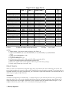
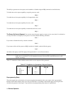
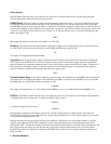
The Serial Poll Register. The serial poll register is an 8 bit register which the supply uses to keep track of its internal
operating status and to determine the operating status of each of its outputs. Table 5-6 defines each bit.
Table 5-6. Bit assignment of the Serial Poll Register
Bit Position 7 6 5 4 3 2 1 0
Bit Weight 128 64 32 16 8 4 2 1
Meaning PON RQS ERR RDY FAU 4 FAU 3 FAU 2 FAU 1
The first four bits (0 to 3) in the register tell whether or not a particular output has a fault. If there is a fault in one of the
outputs, then the corresponding FAU bit will be set. Thus if output 1 has a fault, then FAU 1 will be set. In models with
only three outputs, FAU 4 will always be zero and in two output models, FAU 3 and FAU 4 will always be zero.
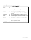
The RDY bit is set when processing is complete and is cleared when the supply is processing commands.
The ERR bit is set when a programming or hardware error occurs and is cleared when the error query (ERR?) is received.
The error annunciator on the front panel informs the user when this bit is set or cleared.
The RQS bit is set when the power supply generates a service request and cleared after a serial poll is done (see page 79).
The PON bit is set at power on and cleared when a CLR command is sent.