


Output Connections and Operating Information
49
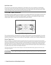
UNREGULATED OUTPUT -- the supply informs the user when output regulation is not guaranteed. This can occur when
attempting to sink excessive currents below 4 volts on 25 W outputs and 2 volts on 50 W outputs or when operating outputs
in parallel. The UNR annunciator on the front panel and the UNR bit in the status register indicate that the specified output
is unregulated. Line voltage dropout or an incorrectly set ac power module can also cause the output to become
unregulated. If line voltage dropout continues, the supply shuts down and will return to the power-up condition when
normal line voltage is restored.
OVERTEMPERATURE -- shuts down the linear pass transistors and downprogrammer of the output that has reached an
unsafe operating temperature. Operation of the other outputs is unaffected. An overtemperature can occur because of
excessively high ambient temperature, a blocked fan, or insufficient space at the sides for adequate air circulation. When an
overtemperature condition occurs, the word OVERTEMP appears in the front panel display and the OT status bit is set.
This circuit resets automatically and restores the output approximately 30 seconds after the temperature drops sufficiently
for safe operation.
ERROR -- if the power supply receives an invalid command either through the front panel or the GP-IB, the ERR
annunciator on the front panel comes on and the ERR bit in the serial poll register is set. The power supply does not execute
the command and remains at previously set values. Pushing the ERR button in local mode displays the error message and
clears the error. The error indicator may also indicate that an instrument failure has occurred. Refer to Appendix D for
further details.
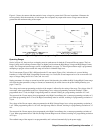
Connecting The Load
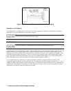
Each terminal block cover on the rear panel is secured by a locking tab which snaps into a slot at the left of the terminal
block. To remove, insert a screwdriver into this rectangular slot and move the locking tab to the left. When the locking tab
releases, gently pull the terminal block cover away from the terminal block. To reinstall the cover, align it over the terminal
block and gently press it into position until the locking tab engages.
SHOCK HAZARD. Turn off ac power before making rear panel connections. All wires and straps
must be properly connected with terminal block screws securely tightened. Replace terminal block
covers before reapplying power.
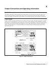
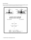
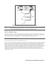
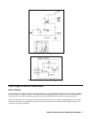
Each rear terminal block has six M3.5 x 0.6 x 6 mm screws for attaching wires (see Figure 2-2). Load connections to the
supply are made at the + V and -V terminals on each terminal block. Do not connect unterminated wires to the load
terminals. Wires used for load connections must be properly terminated with termination connectors securely attached.
Remember to replace the impact resistant plastic covers (Agilent P/N 06624-20007) over the terminal blocks after making
connections.
Consistent with good engineering practice, all sense and trigger leads connected to the rear terminal blocks should be
twisted and shielded to maintain the instrument’s specified performance.
Wire Size Selection
FIRE HAZARD Select a wire size large enough to carry short-circuit current without overheating.
Two factors must be considered when selecting wire size for load connections: conductor temperature
and voltage drop. To satisfy safety requirements, load wires must be heavy enough not to overheat
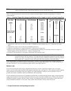
while carrying the short-circuit output current of the unit. Table 4-1 lists the current-carrying capacity
(ampacity) for various sizes of stranded wire.
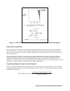
Note that the minimum wire size required to prevent overheating may not be large enough to prevent OV trip when remote
sensing and to maintain good regulation. The load wires should be large enough to limit the total voltage drop in both leads
to no more than 10 volts. See Figure 4-6 for total allowed load lead drop when programming to high voltage settings. With
remote sensing, load regulation is degraded 1 mV per 1 V in the - V output terminal load lead. (See Remote Sense
Connections on page 52).