


Remote Operation
70
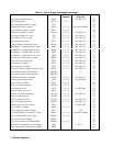
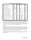
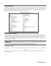
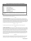
Table 5-2. Power Supply Queries
Query Header
(Note 7)
Channel
(Note 1)
Response
(Notes 5 and 6)
Initial Value Syntax
(Fig.
5-2)
Voltage Setting VSET? 1,2,3,4 SZD.DDD(Note 3) 0(Note 8) Q2
Current Setting ISET? 1,2,3,4 (Note 2) 10 mA (Note 8) Q2
Full Scale Current Range IRSET? 1,2,3,4 (Note 2) High (Note 8) Q2
Full Scale Voltage Range VRSET? 1,2,3,4 ZD.DDD (Note 8) High (Note 8) Q2
Voltage Output VOUT? 1,2,3,4 SZD.DDD (Note 3) -- Q2
Current Output IOUT? 1,2,3,4 (Note 2) -- Q2
OVP Setting OVSET? 1,2,3,4 SZZD.DD 55 V (Note 8) Q2
OC Protection On/Off OCP? 1,2,3,4 ZZD -- Q2
Output On/Off OUT? 1,2,3,4 ZZD -- Q2
Unmask Setting UNMASK? 1,2,3,4 ZZD 0 (Note 8) Q2
Delay Setting DLY? 1,2,3,4 <sp>ZD.DDD .02 (Note 8) Q2
Status STS? 1,2,3,4 ZZD -- Q2
Accumulated Status ASTS? 1,2,3,4 ZD -- Q2
Fault FAULT? 1,2,3,4 ZZD -- Q2
Error ERR? -- ZZD -- Ql
Service Request Setting SRQ? -- ZZD 0 (OFF) Q1
Power-On SRQ On/Off PON? -- ZZD 0 (OFF) (Note 9) Q1
Display On/Off DSP? -- ZZD 1 (ON) Q1
Model Number ID? -- Agilent 662XA (Note
4)
-- Q1
Selftest TEST? -- ZZD -- Q1
Calibration Mode CMODE? -- ZZD 0 (OFF) Q1
DC Power On DCPON? -- ZZD 1 (ON) (Note 9) Q1
S = Sign Z = Digit with leading zeros put out as spaces D = Digit < sp > = space
NOTES:
1. Output channels 3 and 4 are not used in all modes. (See Table 5-4).
2. Current is SZD.DDDDD (0.5 A) & SZD.DDDDDD (15 mA) SZD.DDDD(2 A) & SZD.DDDDD
(0.2 A)
3. Voltage can be SZD.DDDD on 7 VR
4. "X" depends upon model.
5. A space is returned for a + sign.
6. All responses are followed by a <CR> and <LF> (EOI asserted with <LF>).
7. Spaces are allowed between the header and the question mark.
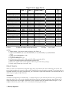
8. Unit powers up with values in state register 0. Table 5-3 gives initial factory settings.
9. Factory setting. Powers up to last stored value.
Order of Execution
When you send a set of instructions to the power supply, they are executed in the order in which they are received. The
power supply completes the execution of the present command before executing another command. To send more than one
command within the power supply command string, use a semicolon to separate the commands. This maximizes the rate at
which the power supply accepts commands.
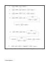
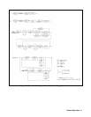
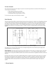
Terminators
Terminators mark the end of a command string. As shown in Figure 5-2, the semicolon, line feed < LF >, and carriage
return line feed < CR > < LF > are the characters that indicate the end of a message to the power supply. When you are
using the Agilent Series 200 computer with BASIC to send a command using the standard format (see Figure 5-1), the
computer automatically sends < CR > < LF > on the data bus following the command.