


Output Connections and Operating Information
52
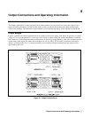
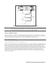
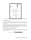
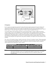
Figure 4-5. Remote Voltage Sensing
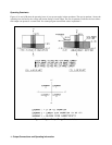
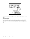
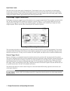
The maximum voltage available at the power supply output terminals during remote sensing (see Figure 4-6) is 50.5 volts.
This allows the sum of the voltage across both load leads to equal 10 volts maximum. For lower output voltages refer to
Figure 4-3.
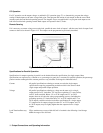
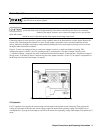
Remote Sense Connections
Remember to turn off the power supply before making or changing any connections on the rear panel terminal blocks.
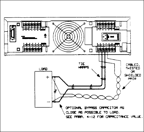
Connect the unit for remote sensing by first disconnecting the straps between sense and load terminals. Then make your
connections as shown in Figure 4-5. Connect the sense leads as close to the load as possible. See wire size selection
(pages 49 - 50) for information on selection of load lead wire gauge. Best results will be obtained by using the shortest load
leads practical. It is recommended that you keep your load leads under 14.7 meters (50 feet) per lead because of inductance
effects.