


Remote Operation
77
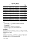
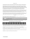
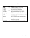
Table 5-5. Bit Assignment for the Status, Astatus, Fault, and Mask Registers
Bit Position 7 6 5 4 3 2 1 0
Bit Weight 128 64 32 16 8 4 2 1
Meaning CP OC UNR OT OV -CC +CC CV
Where
CV = Constant Voltage Mode
+ CC = Positive Constant Current Mode
- CC = Negative Current Limit Mode
OV = Overvoltage Protection circuit tripped
OT = Over Temperature Protection circuit tripped
UNR = Unregulated Mode
OC = Over Current Protection tripped
CP = Coupled parameter (See Note)
Note: When the range is switched as discussed on page 73, or the power limit is exceeded (see pages 71 &
73), the CP bit is set. It is cleared when you send a voltage, current or range value that causes no other
changes.
To query an output channel for its status, you must specify the output channel. For example, to find out the status at output
2 send the following query and address the supply to talk:
STS? 2
Accumulated Status Register. Each output channel of the power supply also maintains a cumulative status in its
accumulated status (astatus) register. This register records every status condition the power supply output entered since it
was last queried. When queried, it returns a decimal number which is decoded as shown below. The astatus register is reset
to the present value of the status register after it is queried. The bits are assigned as in Table 5-5. Here is an example to help
you decode the decimal number (from 0 to 255) returned when the astatus register is queried. If the output channel was in
overvoltage since the last reading of the astatus register and that channel is presently operating in constant voltage mode,
the reading you will get when you query the register will be 9. To decode this we use Table 5-5.
9 = 8 + 1
OV + CV
For example, to query the astatus register of output 2, send the following query and address the supply to talk
ASTS? 2
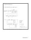
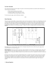
The Mask and Fault Register. The fault register works in conjunction with the mask register. These are two eight bit
registers which report any fault condition on a particular output channel. The mask register is used to set up the conditions
that generate a fault which is latched into the fault register. The user can then read the fault register to determine the fault.
When a bit in the fault register is set, the power supply can generate a service request for that output providing the service
request command on fault (SRQ 1 or SRQ 3) was previously sent. See page 79 for a discussion on service request.
To understand how these two registers work, we must include the status register in this discussion. Recall that the status
register takes its input from the power supply and the user cannot change its contents. The mask register takes its inputs
from the user, and the power supply cannot change its contents. The fault register takes its inputs from both the mask and
the status registers. You can find out the setting of the mask register of output 2 by sending the following query and
addressing the supply to talk:
UNMASK? 2
The response will be a numeric code between 0 and 255 which can be decoded by consulting Table 5-5. You can set the
conditions to generate a fault by setting (unmasking) one or more bits in the mask register. The conditions will remain
unmasked until you change them. To unmask conditions in output 2 for example, send the following command: