


Remote Operation
73
Current Programming
To program the current, send the output channel and the programmed value in amps. In the example below, output 1 is
programmed to 15 mA.
ISET 1,0.015
The value you send must always be in amps. For example if you want to program 95 milliamps, convert to amps and then
send the command
ISET 1,.095
If the output channel is in constant current (CC) mode of operation, then the actual current is the programmed current but if
the output is in the CV mode, the programmed current is the current limit of that output.
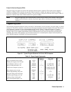
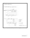
When programming a value of current, the voltage set point can be changed if the total power is greater then the power
boundary (see Figure 4-2).
Example: VSET 4,50 Voltage set to 50 V
ISET 4,2 ISET to 2 A
Sending the ISET command caused the VSET to be reduced to 16.16 V. This is an example where power limiting changes
a supply setting. When this occurs, the "coupled parameter" bit (see Table 5-5) in the status register is set.
To readback the programmed current for output 1, send the query and addressing the supply to talk.
ISET?
You can also instruct the supply to measure the actual output current at output channel 1 by sending the following query
and address the supply to talk.
IOUT? 1
The results are placed on the GP-IB and read into the controller.
Range Programming
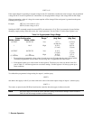
The range can be set by using the VRSET or IRSET commands. The power supply will automatically pick the range that
the value sent will fit into.
Examples: VRSET 1,7 will select the 7 V range
VRSET 1,3.2 will select the 7 V range
VRSET 1,9.0 will select the 50 V range
VRSET 1,50.5 will select the 50 V range
IRSET 1,.015 will select the 15 mA range
IRSET 1,0 will select the 15 mA range
IRSET 1,.020 will select the 0.5 A range
IRSET 1,0.1 will select the 0.5 A range
Note Ranges will accept values up to 1% greater then full scale for voltage and 3 % for current. Larger
numbers will generate a number range error(s).
When going from the high range to the low range, the present setting must be within the boundary of the low range or the
setting will be reduced to the maximum of the low range. If the setting is changed the "couple parameter" bit (see Table
5-5) in the status register will be set to indicate the change.