


Local Operation
89
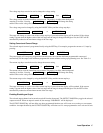
For example, you can change the address of your supply to 10 by pressing:
ADDR 1 0 ENTER
Displaying Error Messages
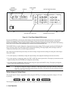
The power supply can detect both programming and hardware errors. Upon detecting an error, the ERR annunciator on the
front panel comes on and the ERR bit in the serial poll register will be set (see page 78).
When an error is detected, you can display the error message by pressing the ERR key. The power supply will return the
error message to the display and clear the error bit. For example, if you program a number that is not within the valid range,
the ERR annunciator will come on. You can display the error message by pressing the ERR key. In this case, the error
message "NUMBER RANGE" will be displayed. Errors generated either locally from the front panel or remotely from the
GP-IB computer can be displayed by pressing the ERR key only when the supply is in the local mode. Pressing the ERR
key also clears the error bit so if you press ERR again, the message "NO ERROR" will appear. All error codes and
associated display messages are listed in Table 5-8.
Storing and Recalling Voltage and Current Settings for All Outputs
As described on page 75, the power supply has 11 internal registers for storing voltage and current settings of all outputs.
At power on each location contains zero volts and the minimum current limit (see initial conditions on page 71).
The STO and RCL keys allow you to store and recall voltage and current settings for all your output channels from any of
the 11 internal registers (numbered 0 through 10). For example, you can store the present settings of voltage and current for
all the output channels in internal register 2 by pressing:
STO 2 ENTER
You can change the settings of any of your supply’s outputs any number of times as required and then program them to the
settings stored in internal register 2 by pressing;
RCL 2 ENTER
The internal registers 0-3 will retain the settings when power is turned off. When power is turned off and then on again,
registers 4-10 will be reset to zero voltage and the current to 10 mA. Register 0 is the power on state. The power will be
programmed from values in register 0 at power on.
The advantages in using the internal registers are that command processing time is saved and repetitive programming of
different settings is simplified. The STO key can be used in conjunction with the OUTPUT ON/OFF key to store settings
while the outputs are disabled (OFF). These stored settings can be used later to program the outputs to the stored settings
using the RCL and OUTPUT ON/OFF keys.